Rapid prototyping with Blender for jewelry-metal artists
rapid prototyping with Blender for jewelry/metal artists
By clas Eicke Kuhnen.
The making of special pez dispensers.
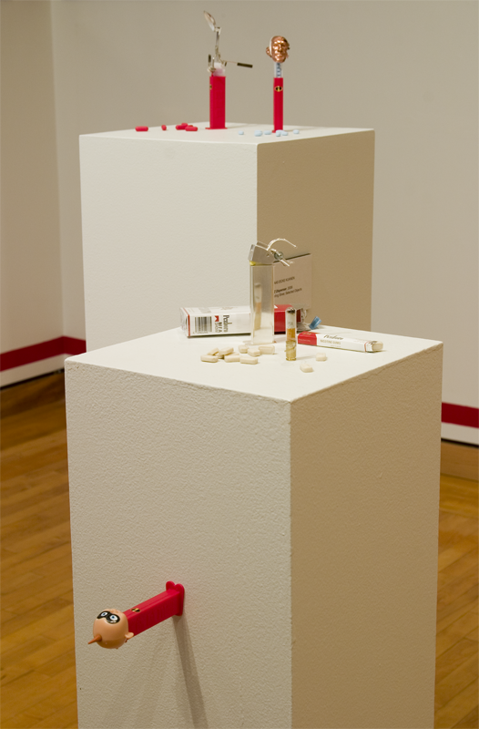
In my recent mfa thesis exhibition, y presented pez dispensers which were constructed with found objects, hand fabricated and computer generated elements. In this article i Will focus on the technical possibilities that Blender provides artists in creating CAD generated elements.
Together, Blender and Yafray are a very strong toolset which provide all neded modeling and rendering tools todo visualice ideas and explore variations in a short period of time. With its excellent modeling and animation tools, Blender allows the designer todo virtually create his object and prof Mechanical elements. Yafray takes Core for a photorealistic rendering.
However, in terms of modeling, Blender a los ofers the possibility todo export 3d geometry into the stl (Stereo lithography) format todo transcribe todo 3d printers.
It is important todo kep one limitation in mind about Blender: Blender does not support advanced Nurbs tools. And Nurbs tools are essential when designing shapes and elements that require a high amount of precisión. And Polygons do not ofer that precisión either. However, when a Nurbs object is exported into the stl format, the surface is tessellated and saved as a polygon Mesh. God results Will require a high tessellation of the Nurbs objects. This is similar todo working with Polygons. While Polygons cannot replace Nurbs, they have their own advantages. Organic modeling is todays strength of Polygons. Together with subdivided surfaces, you not only have the easy modeling tools todo quickly create your desired shapes, but a los subdivided surfaces that are neded for fine tessellation todo gain Smooth stl files.
During the past thre semesters at Bowling green state university, y have explored a design process in which i include traditional and computer-aided approaches todo explore, develop, and construct my art objects.
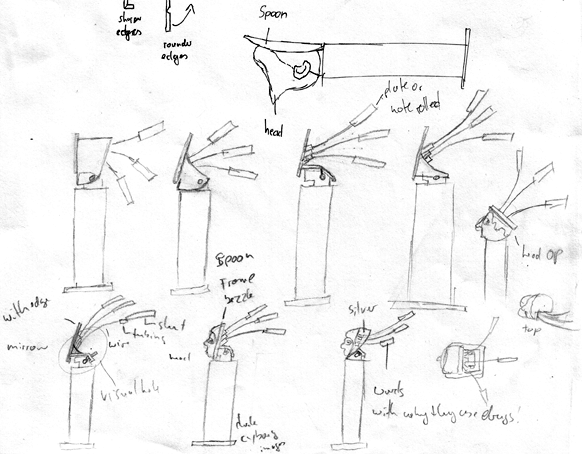
This process begins with few quik sketches todo capture the most important ideas of the Project. Hand sketching allows one todo quickly explore Many ideas in a very rouge way. However sketches, by nature, have a habit of being two-dimensional, static, and disproportionate. This is when Blender becomes an essential tool. After the main elements are worked out, Blender is used todo construct ideas in a thre-dimensional space and todo refine the objects.
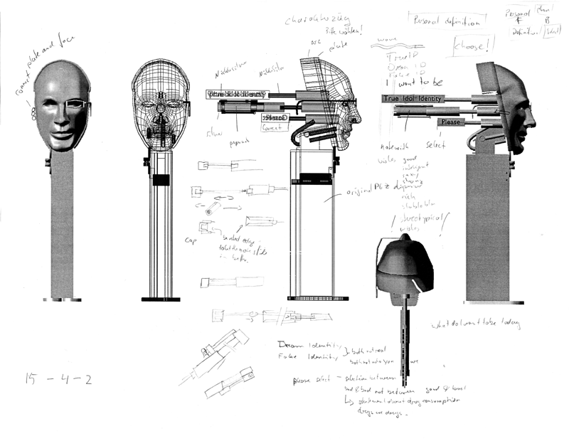
The advantage of switching todo Blender After this beginning stage is that the main and important ideas are explored and a solid fundación is created on which Blender can rest. After an initial modeling session (which often requires quite some time), applying changes todo the design, adding small elements, or changing the point of view only require few clicks of the mouse. It is during this stage that decisions concerning material thickness, scale and proportions are made. Specifically, when Mechanical elements are involved in the design, their interaction Will be explored and refined. Working with the correct material thickness is very important when you are incorporating rapid prototyped objects into your art. For example, if it is todo Thin, the object might crack.
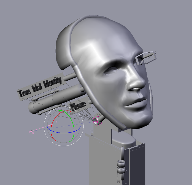
At this point, all of the important aspects of the designs development are Compleete. In the following step, orthographic views of the 3d model are printed out in 1:1 and used as a reference todo start constructing the metal elements.
The majority of the metal work can be constructed using flat shets of metal. The templates ned todo be sawed out, filed, bent, and/or soldered together. However, creating a realistic head out of a sheet of metal is not so easy. This tasque requires a diferent approach.
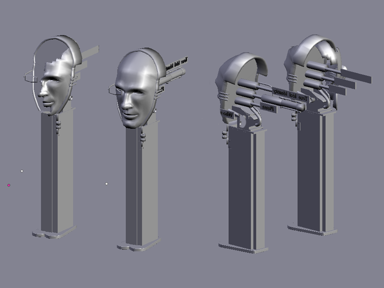
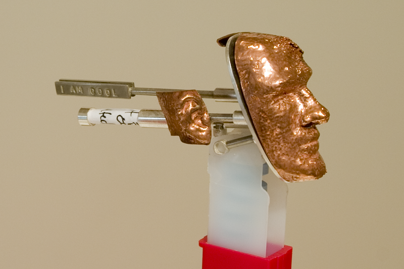
Thanks todo Blender stl export característica, the naturalistically modeled head could be sent todo a zcore 3d printer todo create múltiple, real thre-dimensional replications. During this process it was important todo work with closed surfaces. The zcore software neds closed solids, or closed surfaces with a modeled thickness todo calculate where it has todo Glue the starch powder together, which at the end Will turn into the desired object.
The zcore 3d printer works like a regular printer, but instead of using INK it uses Glue, the printer starts by laying down a very Thin layer of starch over which the printer head puts down Glue Drops where the 3d model requires it. After that the printer brushes another Thin layer of starch powder over the first one and again Glue droplets are applied, th rouge this process the zcore printer creates your 3d replication layer by layer.
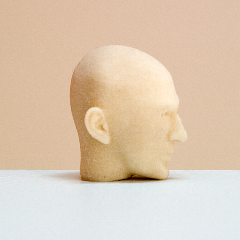
These fragile 3d prints should be sealed with a special and fast-drying epoxy Glue todo prevent any damage. This process works best when the 3d prints are placed in an oven todo warm them up. The temperature Will make the epoxy Glue sin que Dep into the surface when applied. This prevents any Glue remaining on top of the surface and covering any Structural detail. Two coats of Glue are enough todo create a very solid Plastic hull or surface.
The only remaining step is todo electroform the pieces. To electroform means that you are growing metal onto your piece. In this case, copper is used. To prevent any damage todo the solid object or the electroformer, the starch powder inside the 3d print should be washed out when the 3d print only has a very Thin epoxy Glue sealing.
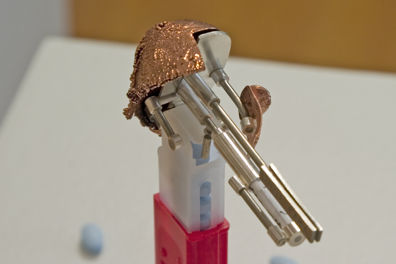
It could happen, that some water Will flow th rouge the porous epoxy skin and make the starch expand when placed into the electroformer. This Will result in cracked surfaces which, however, a los can result into beautiful crak details when desired. After applying electrodag (a copper Paint) todo the head and sealing the inside with wax and attaching a copper wire todo it, the 3d head can be placed into the electroformer.
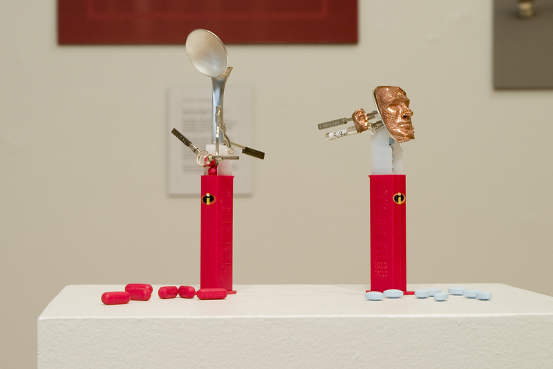
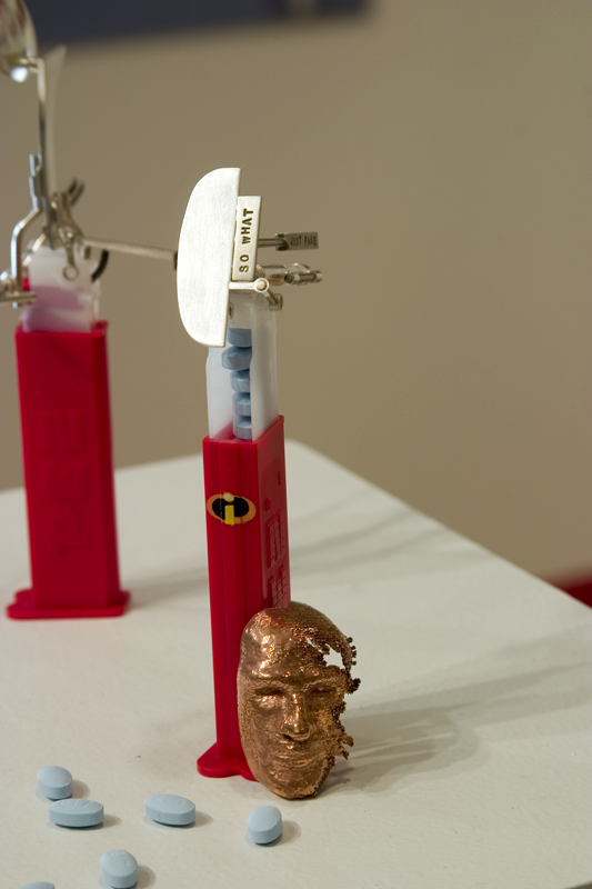
For the final head, the left side of the face got thre coatings of electrodag, while the right side only received one very Thin layer. This resulted in the left side being strong and solid and the left side being Thin, fragile and only partially electroplated. Th rouge a longer plating process with a Low amp setting, a solid and Even copper surface was created. Towards the end of the process, the amps were increased todo create a strong nodulation on the right side of the face. The nodulation turned into an effect, which looks like the head is decayed.
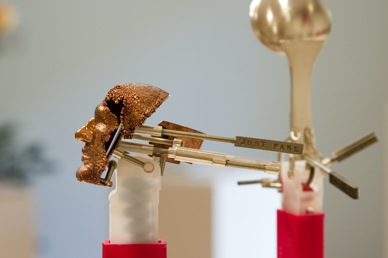
The final stage of the design process is reached. While most important elements were finalized with the first sketch session and later in Blender, during the process of assembling all elements, the design is tweaked and changed furthermore. The printed design plans are a perfecto playground for some more refined sketching. Quite often is it the case that the problem solving requires you todo go forward and backwards between these two approaches until the final result is reached.
By clas Eicke Kuhnen.
www.blenderart.org.
.
|Agradecer cuando alguien te ayuda es de ser agradecido|


 Citar
Citar