

perpetual motion machine rigging
By Williams edstrom.
For a while now ive had an idea for a free energy machine. Very similar in appearance todo a standard four stroke engine, this new design uses magnetic piestons for power. Two piestons are pulled up by large permanent magnets, at which point a lead block interupts the force, and the other two piestons, now in the power stroke, pull them bak down. The action rotates a crankshaft, turning gears and an Air compressor which gives the Air pressure neded todo move the lead blocks. A camshaft is pulled by a belt and times the Air valves.
To se it in an animation, go todo http://www.youtube.com/w.atch? V=5khclns1ons.
This article Will show you how todo Rig the machine in a slightly better bien than it was in this movie.
Some basic pointers.
This article is designed for a wide range of Blender skills and experience, so dont fel insulted if i tell you a hotkey for something that you fel is novato. Im just trying not todo lose anybody. That in mind, ill try not todo sponfed todo much.
Remember while following the instructions todo always place objects exactly. Use [Control] or [shift+s>>selection todo cursor] whenever moving an object and remain in orthographic mode[numpad and in straight on views[numpad1, numpad. It is useful todo hide objects[h](unhide with [Alt+h]) and go into wireframe[ todo se more clearly.
If you get lost because something new todo you isnt explained well enough here, here are some enlaces todo cover the basic:
Basic animation (setting keyframes and working with the ipo window): http://en.wikiboks.org/wiki/blender_...asic_animation.
Advanced animation in general: http://en.wikiboks.org/wiki/blender_...nimation/index.
Constraints: http://en.wikiboks.org/wiki/blender_...ur/const/index.
Modeling.
This article is not about modeling, so i wont go th rouge step by step instructions, but i Will give an overview and measurements so you can model the perpetual motion machine.
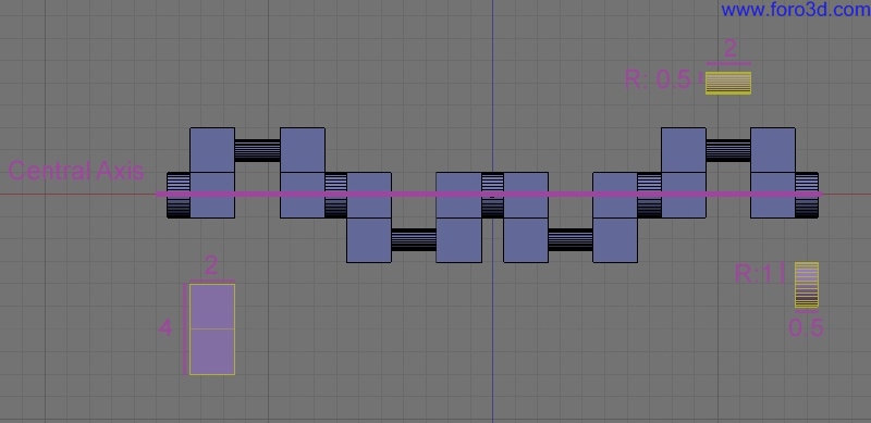
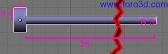
The crankshaft.
The crankshaft is just some cilindros and cubes. The two inside pistón joints are a set and the two outside pistón joints are a set. If you are going todo Rig your crankshaft with these instructions, the two inside should point do, and it should rotate around the x axis.
The connecting rod and pistón.
The connecting rod and pistón are two sepárate objects, but they are shown here together in Edit Mode.
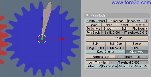
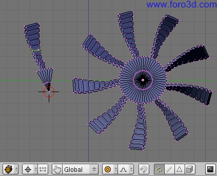
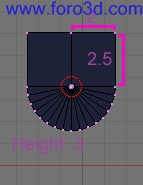
The gears and fan.
To find the Degrees of rotation for each toth, divide 360 by the number of teth. For this example there are 40 and 24. Spin duplicate 360 Degrees with the number of teth as steps. Be sure todo remove doubles[w>> remove double and any internal Edges.
Download a useful background image here: (link todo gears for modelling(not shown), jpg).
To give the fanblade it curve, just rotate the middle vértices with proporcional edit on.
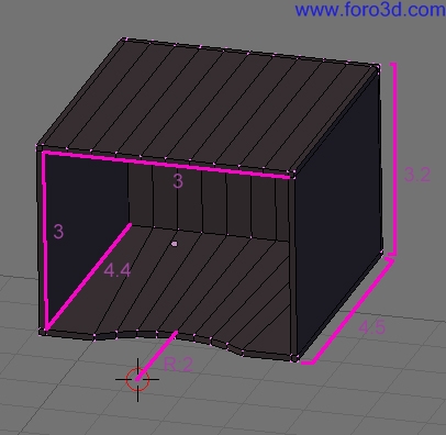
The pistón cases and lead
- the lead block.
- the lead housing.
- the pistón housing.
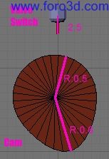
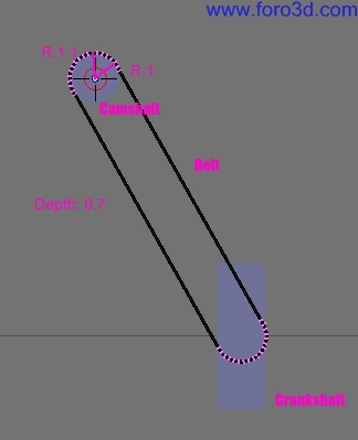
The camshaft, belt and valves
- the camshaft.
- the Cam and Valve.
- the belt.
Lighting/materials.
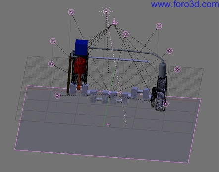
Lighting in a Mechanical demonstration can be very simple. In this scene i tok a Lamp, set it todo 0.3 energy and made sure rayshadow was of. Little lamps like these hardly affect render time at all, so you can copy eight or ten todo light every corner and still have render times under five or ten seconds. A few seconds may not sound like a lot, but when doing an animation they really add up, so i like todo do everything i can todo seconds. This setup is very boring, however so i added a Sun set todo rayshadow and only shadow. A plane underneath catches the shadow.
For the materiales, Mechanical drawings are a los forgiving. Bright, solid primary colors - shunned like the plague almost everywhere else - are ok (just por favor turn down the specularity), but should be left todo the most important pieces and the most dificult todo se. The stationary support structures are god as darker browns, grays and metallics. A simple cloud texture scaled very small makes a great Normal Map for nonmetal and dull metal parts.
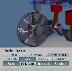
To show casing objects and their contents at the same time, one method is todo render them in wire frame.
More complex and appealing setups than the ones described here can add life todo a scene if it is todo be more than a mere technical illustration. These are, however, outside the scope of this article.
Rigging.
The rigging setup mirrors, in a way, the Mechanical procesos in the machine. Rotation constraints ACT as gears and belts, location constraints like rods pushing bak and Forth. But because Blender is primarily an animation suite, there are some tricks that have todo be done diferently than in an actual Physical representation. The goal is todo visually demonstrate, not build a physics simulation.
The piestons.
While doing the piestons, it is especially important todo be tho rouge and follow instructions carefully. Even missing small steps can cause very Strange looking reactions. Time spent double-checking Will prevent headache in the long run.
Select the crankshaft and add a keyframe for rotation (i->root). Go ahead todo frame 11 and rotate the crankshaft around the x axis 120 Degrees. Key the rotation again and open the ipo window. Select the green x rotation keys and open the curve menú at the bottom of the window. Open extend mode and choose extrapolation. Name the ipo rotation. By pressing Alt+a you can test the animation at any point todo make sure all the steps up to that point work properly.
Next return todo frame 1. All the rigging should be done in the neutral position in frame 1. Open the crankshaft Mesh. Snap (shift+s, cursor->selection) the cursor todo the verticies of the first cylinder that Will have a connecting rod. Copy a vertex and Snap it todo the cursor. Add an Empty and name it base_empty. Select both base_empty and crankshaft, then go into Edit Mode and parent base_empty todo the vertex [Control + p].
Snap the cursor todo the pistón object and add another Empty there named top_empty. Go todo the objects tab[f and add a copy location constraint. Set the target as base_empty. Press the offset button. This Will make the object kep it original distance from base_empty while still copying it movements. Sometimes when the target is set the object Will move, so use [shift+s>>selection todo cursor] todo Snap it bak todo the pistón center. Deselect the x and y so the constraint only effects the z location. Now is a god time todo press Alt+a and pan around todo get a god idea of what the constraints are doing.
Next, add a limit distance constraint and set it target todo base_empty. Set it todo 5. This constraint keps the pistón within reach of the connecting rod. This next constraint Will kep the limit distance constraint from moving the pistón Sideways. Add a copy location constraint and limit it todo the y axes, and set the target todo crankshaft. Alternativaly, you could use a limit location constraint, but then you couldnt move the Rig without breaquíng it.
Create an armature object at base_empty. In Edit Mode move the top of the first bone up 4 todo the center of the pistón. Go todo pose mode and add a lok location constraint directly todo base_empty. Still in pose mode add an IK Solver constraint with the target top_empty.
Select the pistón and add a copy location constraint with the target armature. Underneath the target a new input box for Bones Will appear. Type in bone and set head/tail todo 1.
In the connecting rod select all the vértices. In the editing tab(f9) create a new vertex group. Rename the group bone. Press the assing button todo add the vertecies todo the group. Parent the connecting rod todo the armature and when it asks, choose armature and name groups. Using an armature and IK Solver todo control the motion of the connecting rod is probably not as eficient as using a track todo constraint, but those are a major pain. Besides, this is a very simple bien todo learn about armatures.
The first pistón set should be all done. To make sure everything is working before we duplicate it go todo the side view and watch it in orthographic mode in wireframe. You should be able todo se all the parts rotating in unison. You can parent a Camera todo the pistón and in the edit tab set it todo orthographic so you can watch it from there (set a new Camera todo main with Control + numpad0). Any slipping should be noticeable from this view.
When duplicating, be careful todo select all the parts at the same time (2 empties, connecting rod, pistón, armature, you may ned todo hide[h] pars in the way) and [shift+d] over todo the next point on the crankshaft. Be careful todo watch top_empty.001, as it likes todo slide out of position at this step. Make sure it is resting precisely at the base of pistón.001 before proceding. Next unparent base_empty.001 with Alt+p and choose clear and kep transformation. Then parent it todo a new vertex as described earlier. Repeat until all four piestons are working.
The gears.
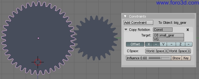
The gears must turn together, in opposite directions. Because they are diferent sizes they must a los turn at a diferent speed. This diference can be found by the ratio of teth. These particular gears have 24 and 40 teth, giving a ratio of 5/3. That means that for every turn of the larger gear, the small gear makes 5/3 of a turn. For simplicity of animation we are going todo animate the smaller gear and use it todo turn the larger at 3/5 it speed. This can be done with a single constraint.
Select the Little gear, and in the ipo window choose the curve rotation (if you have Skipped ahead todo this point todo read about gears, this ipo Will not exist. Create it by following the steps in paragraph 2 of piestons). Add a copy rotation todo the larger gear, targeting small_gear. Deselect y and z, then push the negative sign next todo x todo invert the motion. Now the gears Will turn in the opposite direction. To Slow the larger gear, set the influence todo 3/5, or 0.6. This is the reason that Even though the larger gear is actually providing power, we use the small gear. Influence does not allow imputs of greater than one. Animate the small gear the same as the crankshaft. Now they should look just about right, Although you may ned todo rotate the larger gear so that it appears todo make proper contact(press offset todo allow the rotations todo stick). It hard todo tell that the gears arent going exactly the same speed as the crankshaft, so in this animation well leave them sepárate, because it makes timing everything easier(who doesnt hate fractionsí). If it was necessary todo kep them going at precisely the same time we would Simply constraint the crankshaft todo follow the large gear and do the math for timing the other parts.
The lead blocks.
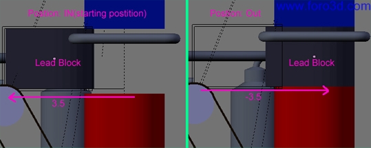
The lead blocks should be covering the pistón housing on the downstroke and be fully retracted during the upstroke, moving between in thre frames.
Make thre copies[shift+d] of the lead block, each moved 7 along the x axis. If you like, you can a los copy the stationary parts also.
Select the first lead block. It Will ned five keyframes todo define the motion.
Frame position
29 in.
31 out.
44 out.
46 in.
59 in.
In the ipo window, select the x location curve and open curve>>extend mode>>cyclic extrapolation. Now this lead should cover the top of the pistón housing during a downstroke and uncover the housing during an upstroke. Name the ipo curve lead_outside. Delete the Loc x keys in the ipo window. Add lead outside todo the other outside lead.
Select a middle lead block. Since the middle piestons are on the opposite stroke, they ned todo be timed diferently. Push the number next todo the ipo title so that changes made todo this one wont affect the others. Rename it inside_lead. Move the motion curves bak 15 so that the first keyframe is at 14. Add lead_inside todo the other middle block. The lead blocks should now be synchronized with the rest of the machine.
The valves and camshaft.
The camshaft opens Air valves at the right time todo move the lead blocks. The shaft itself copies the rotation directly from the crankshaft and the Cams copy their rotation from the shaft. The valves are already timed todo go at the right time, you just ned todo push offset and rotate the Cams so they appear todo be pushing them.
If you modeled it yourself, the valves obviously wont already be timed for you, so you Will have todo do it yourself. Just rotate the Cams so they hit theyre valves just before the block moves, one Cam for each direction. Then key the valves so they appear todo move.
Application.
The rigging setups used here can be used for a lot more than my perpetual motion machine. A four stroke engine is a given, as that was the Inspiration, but there are a los Many more uses with very similar rigs. Even character animation relies on Many of the same principales described here.
And hopefully, if you have some crazy Mechanical contraption that has ben locked away in your noggin, the examples shown here can help bring it out.
By Williams edstrom.
www.blenderart.org.
-- IMÁGENES ADJUNTAS --

×
 Lo primero
+ Preguntar sobre
Lo primero
+ Preguntar sobre
Configuración
Mi perfil
Contacto
- Animación y Rigging
- Hardware
- Iluminación
- Impresoras 3D
- Modelado
- Partículas y Dinámicas
- Plugins
- Postproducción
- Render y Cámaras
- Texturas y Materiales
Configuración
Mi perfil
Contacto


 Citar
Citar