

 Use of Blender as nurbs Cad application
use of Blender as Nurbs/Cad application
By clas Eicke Kuhnen.
Preface:
I created Blender files for this article. Pléase fel free todo look into it while reading.
Introduction:
Class-a Nurbs and Acis solids are the preferred tools of choice in industrial design and product enginering. Those tools provide the designer with the enginering requirement and artistic Freedom.
In addition todo those tools most High End applications a los provide a true construction tre. This is similar todo the history in Adobe Photoshop. However the diference is that it enables you todo change properties of your design without having todo remodel all following steps. An Edge fillet for example for solids is called a característica. It is interactive and not permanent.
The nice aspect of Nurbs and solids is that in most packages like ashlar Cobalt you can convert a closed Nurbs object into a solid and apply functions like bolean operations or complex Edge fillets. Afterwards the solid can be Split into individual Nurbs patches which reflect the applied solid tools.
Blender in contrast does not provide any of those techniques. However if you pay attention todo the current software market for industrial design products you Will notice that more and more companies include complex polygon Mesh tools into their packages which go beyond the rudimentary import function.
With Rhinoceros 4 McNeil increased significantly the polygon Mesh tools. But they mainly are still limited todo clean up work, not for surface creation. Everybody who works with Nurbs and a construction tree values the flexibility and precisión it provides. However Nurbs a los has its límites. For Many years, Autodesk Maya has had the ablity todo convert 4 sided polygon meshes into subdivisión surfaces which than can be converted into Nurbs patches.
And recently t-Splines a los brought their t-Spline technology as a plug-in into Rhino. T-Splines in contrast todo Mayas subdivisión ofers the possibility todo work with subdivisión surfaces like in Blender, but additionally has the ability todo locally add additional Edges onto a face. This can result in Faces with more than 4 Edge points.
This is very familiar todo traditional Nurbs patch modeling of a face. In Nurbs, Edge curves can occupy the same space while having a diferent amount of control points. However the contrast is that with Nurbs you handle stitched patches, with t-Splines you work on one Mesh object only.
T-Splines inside Rhinoceros 4 can then convert the subdivisión model into very optimised Nurbs patches todo enable the designer todo apply Nurbs specific tools todo the model like fillets, blends, or trim surfaces for example.
However as great this is, the work-flow with t-Splines polygonal Mesh modeling in Rhinoceros is limited. Rhinoceros is a Nurbs modeler and t-Splines brings some basic Mesh modeling into Rhino. This is where Blender with it quite powerful Mesh modeling tool set comes in.
Subdivisión modeling todo Nurbs work-flow:.
This illustrates the new possibility of a designer todo not only rely on Nurbs and solids but a los todo utilice polygon Mesh modeling with the usage of Catmull Clark subdivisión surface smoothing todo create surfaces - Which are rather dificult with Nurbs or solids.
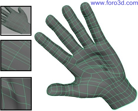
Polygon Mesh modeling never played an important role in product design. A main reason for that is that a polygon model provides internally only linear Edges while Nurbs surfaces are always smooth.
The same still applies todo when you increase the density of the Mesh.
A common trik todo make a Mesh model look Smooth is todo turn on vertex normal smoothing which simulates a blending between Faces. However this is just a simulation - Looking straight onto an Edge reveals the true linear geometry structure.
In a nutshell you can explain Nurbs as computed surfaces which are based on math calculated curves. Surface structures can thus be calculated by curve projections. Mesh modeling is comparable todo working with linear wire sticks. Surfaces structures are modeled by hand.
However what sems at first a disadvantage, and that is how polygon Mesh modeling was treated in the past, can be very useful for Even CAD applications.
The magic Word is 4 side polygon modeling with subdivisión surfaces.
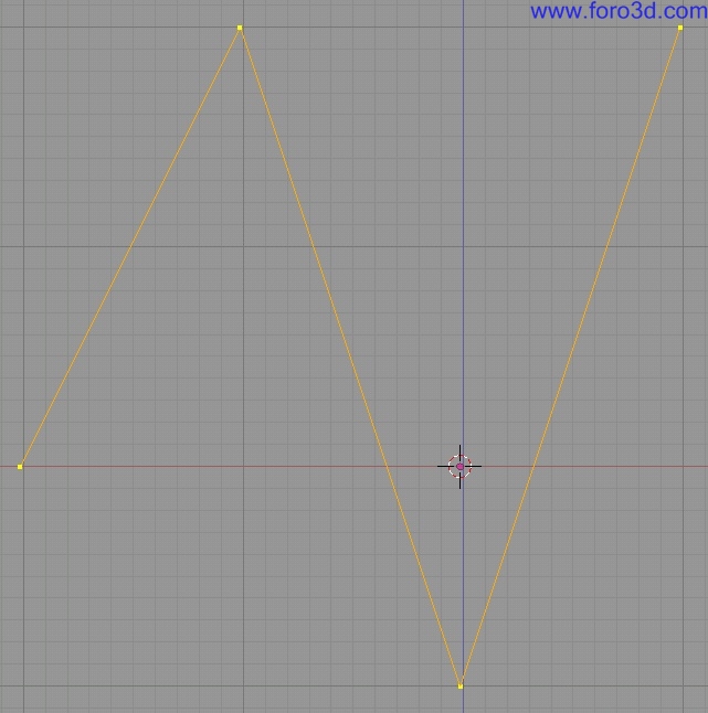
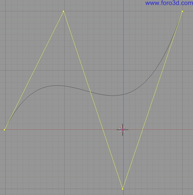
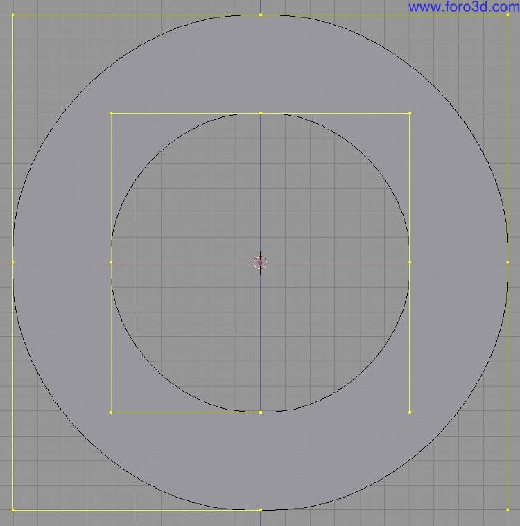
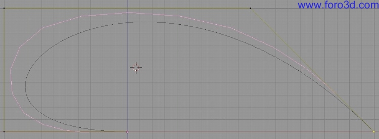
Blenders subdivided surfaces behave very much like Nurbs surfaces. Lets compare a 4 point Nurbs curve with a Catmull Clark curve. The similarity is that the two curves flow th rouge the start and end point without touching the points in between. The diference is of course that Nurbs is Smooth and you can se the linear sub-segments of the subdivisión surface curve.
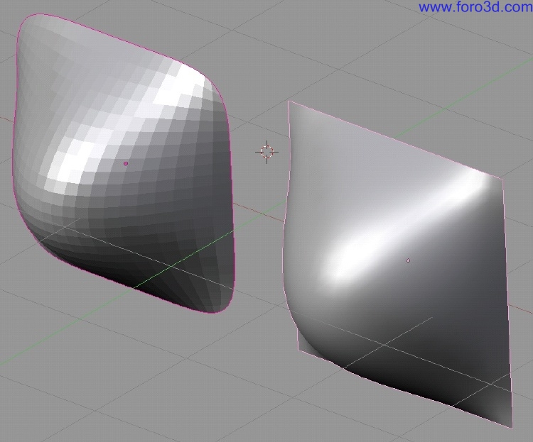
The same nearly applies todo surfaces. The diference you can se is that the Nurbs curve is spawned perfectly inside the 4 sided control patch while the subdivided surface does not flow from Edge todo Edge - Instead the Edges are round.
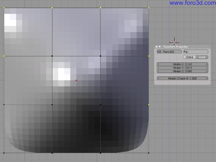
However this can be changed by applying a full crease weight todo the patch Edges similar todo Nurbs weight option.
The important aspect behind this comparison is that instead of modeling straight in Rhinoceros for example, the designer could sketch out the basic model in Blender, import it into Rhinoceros todo finish it up there. Subdivided surfaces allows you todo extrude Faces while Nurbs can Cut holes, trim parts away, and create blends which match perfectly the tangency of the two connecting Edges of two objects. With the possibility todo turn a polygon Mesh into matching Nurbs patches utilizing a subdivided surface algorithm, the best of both worlds are combined.
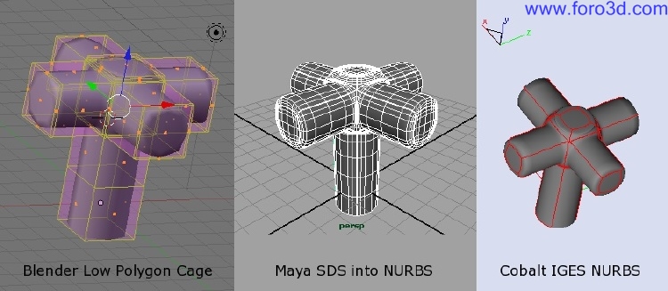
As a quik example, por favor take a look at the following image. It shows a very rouge model of a water faucet. Modeled in Blender using a Low polygon Cage exported that is then imported into Maya and converted into SDS and then into Nurbs. From Maya exported as IGES into Cobalt. As you can se there is no loss in detail. Modeling this object in Blender including converting it th rouge Maya was faster than building the object in Rhinoceros straight with Nurbs. Pay attention todo how the surface between the horizontal 4 extrusións flow into each other and vertically along the main shaft of the faucet. A simple looking but quite labor intensive work.
Case study 1: surface Shell and chamfer creation.
In my last CAD class i introduced my students first todo Blender as a modeling application utilizing subdivisión modeling as a basic introduction into how todo think in 3d and how todo create surfaces. The first major Project was todo design the new i-pod shufle. This product ofers Many aspects todo learn:
Part 1:.
Extrusión of profiles, creating fillets and Chamfers, and creating planar surface fillings between diferent profiles. In addition, it made heavy use of Blender Snap and scale along axis constraints in conjunction with the 3d cursor. Working in proportions and using Blender measurements.
1. Pre-planning:
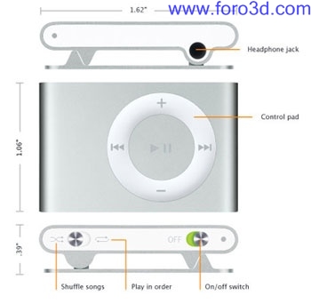
Measurements, the big concern in Blender for new users can be approached in a very simple way. Th rouge utilizing a technical drawing of a new IPod shufle the students were quickly able todo work in correct proportions.
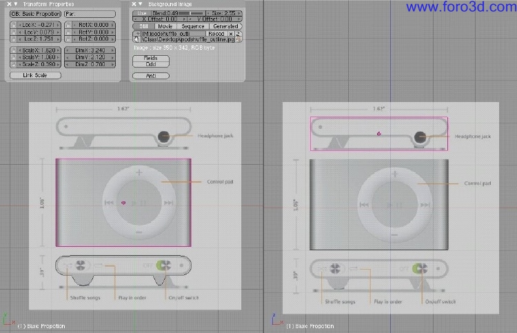
However, the supplied dimensions can be used as well. All that was required was todo scale a box todo 1.62 todo 1.06 todo.19 todo create the rouge dimensions which represent the IPod. While Blender does not supply you with any unit system, you can still use the Blender units and decide on your own what they represent. In this case 1.62 in Blender were equal todo 1.62.
We ned todo do this todo the 3d object and afterwards a los todo the Mesh inside. This bien the 3d body has the same measurement values as the 3d Mesh. Additional measuring of parts by hand helped todo more carefully model all neded parts. Afterwards we scaled down the image todo fit the box dimensions.
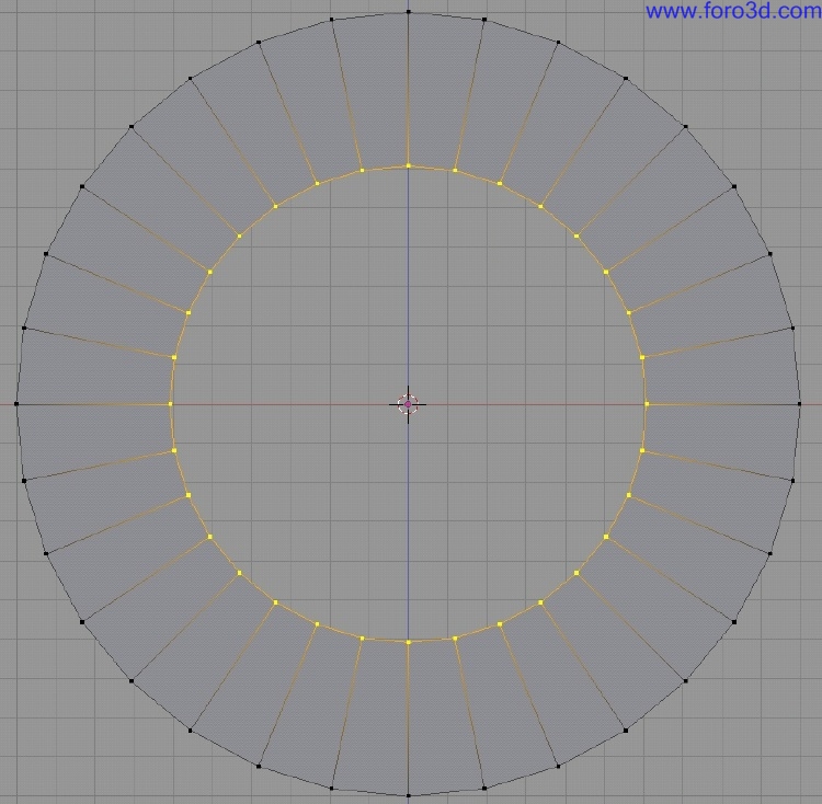
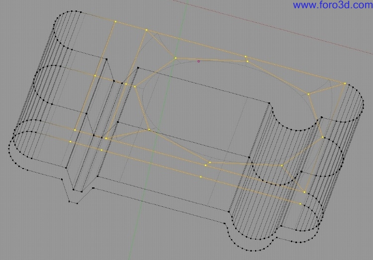
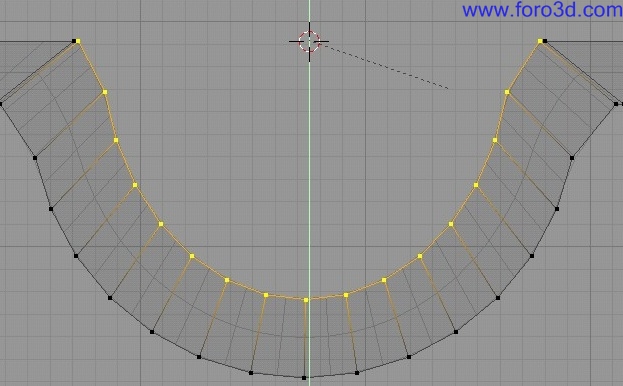
2. Shelling sides: we started with drawing out the top profile of the main body using the straight lines for the sides and half rings with 32 vértices. From the beginning we used the subdivided surface modifier todo create Smooth curves. In the profile we a los already built in the Edge blends todo form Smooth transicións in the corners.
We a los subdivided the one Edge which is above the radial button todo build in the geometry we ned todo build in the round hole for the radial button later. This required some proper pre-planning before modeling.
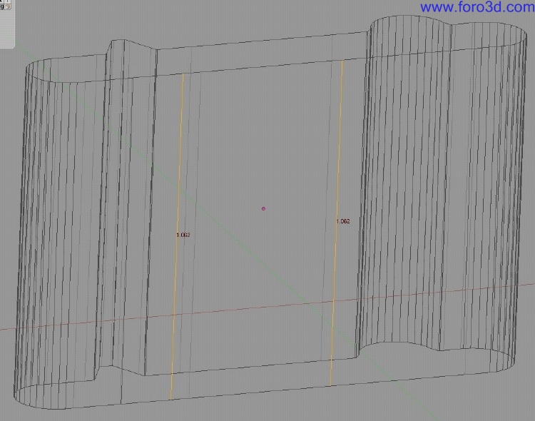
After that we can extrude the profile todo the desired length. By turning on the Edge length, we can make sure todo perfectly hit the right values.
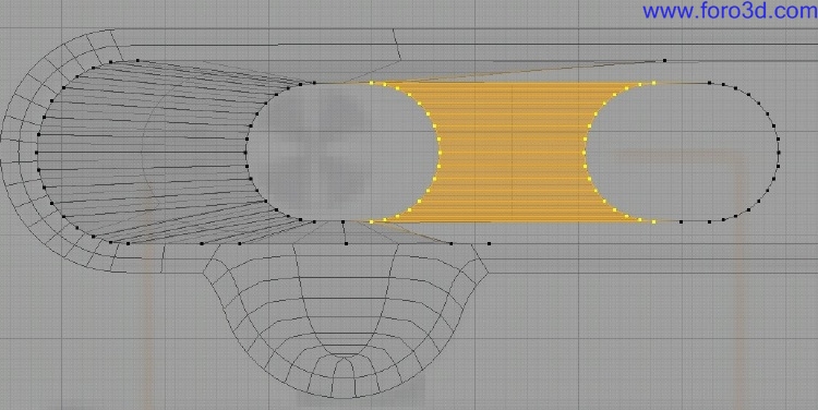
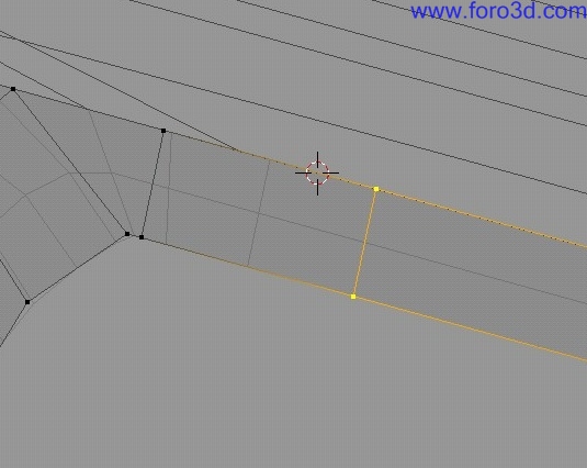
A four sided face does not produce a perfecto round circle, thus we ned more than 4 sides. For a god Nurbs topology we can use a 8 sided circle. To Stitch that in, we add a horizontal loop Cut todo build in the ring opening.
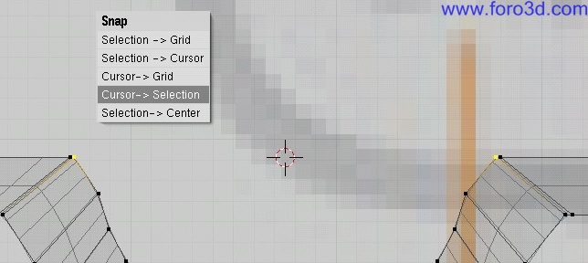
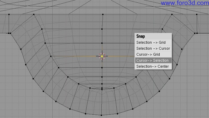
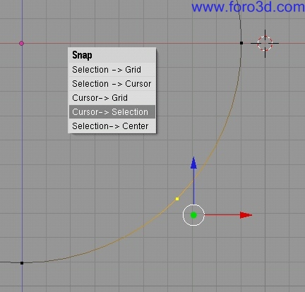
After removing the Edges where the ring has todo be inserted, we utilice Blender Snap 3d cursor todo selection (shift s) todo position the 3d cursor at the right position.
We scaled down the ring todo the proper size and then start filling in the rectangular Faces in between.
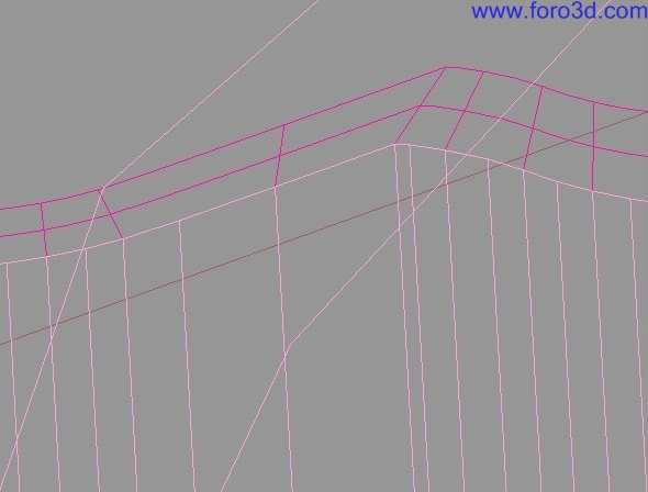
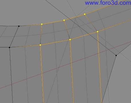
3. Shelling tops:.
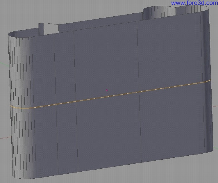
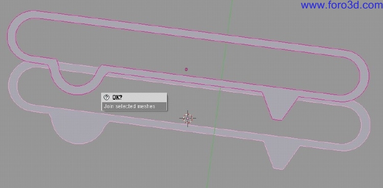
The main side is done now. It is very important that we continúe working with the same profile of the side todo create the Faces for the top shells. The reason behind it is that only when the Mesh points of neighbour Edges of diferent Mesh patches are at the same positions Will we prevent any gaps between surfaces and guaranty creating a water prof model, meaning a solid. The following screen shots 1 object mode and 2 with both objects joined shows the concept behind this.
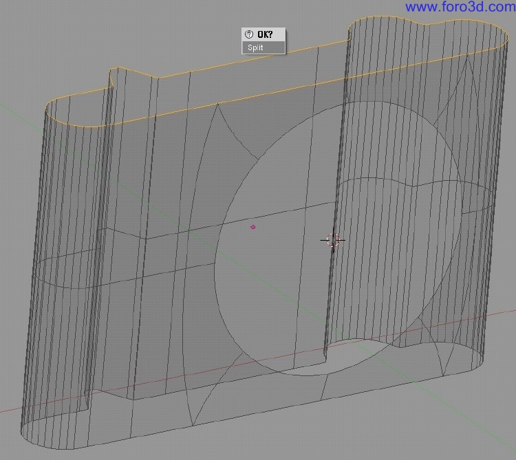
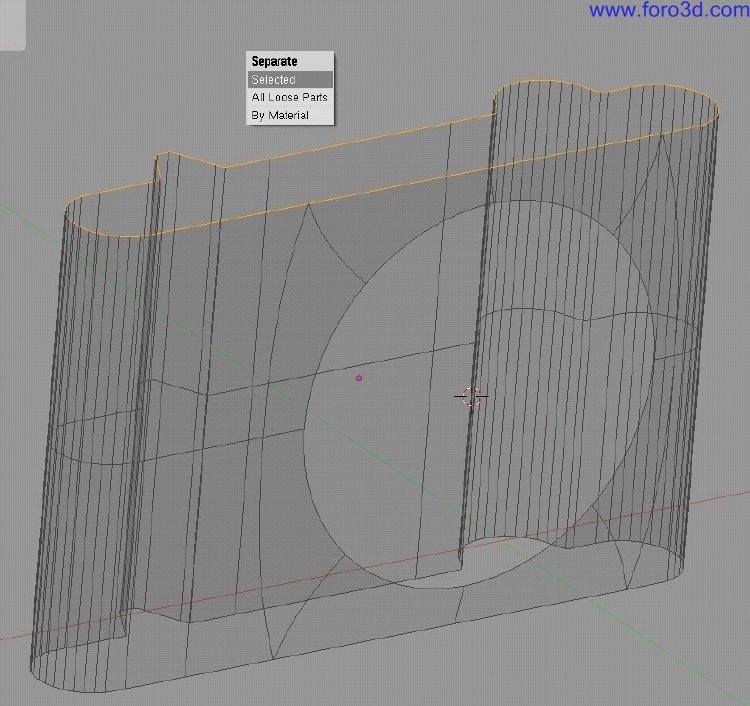
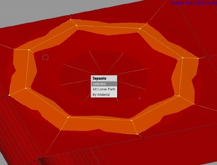
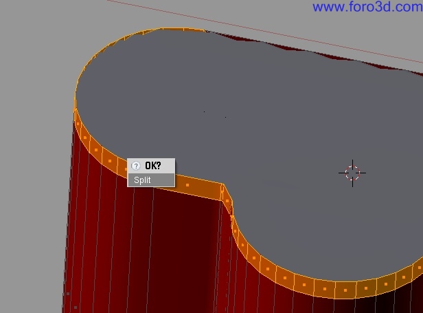
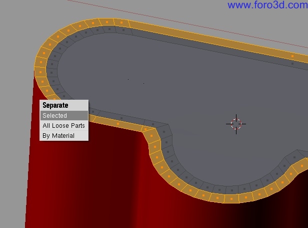
We can select on the ring and hit y todo Split the the ring - It duplicates and disconnects the selection - And then sepárate it with p into a new 3d object.
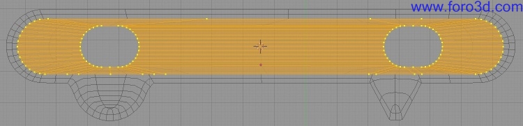
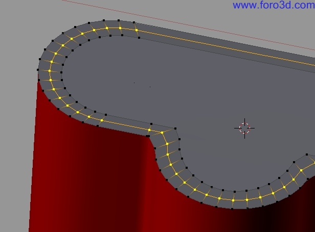
It is time todo start working on the top Faces. Blenders internal offset tool Shrink does not always work very god or correctly. Because this IPod is quite simple todo model, we can utilice a simple combination of scale and move steps todo create the proper first ring on the top face. Use the extrude tool first and then scale and move objects todo your ned.
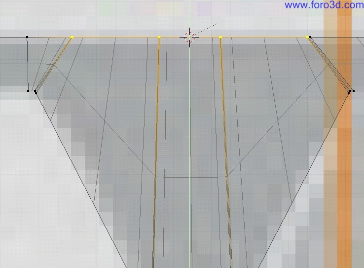
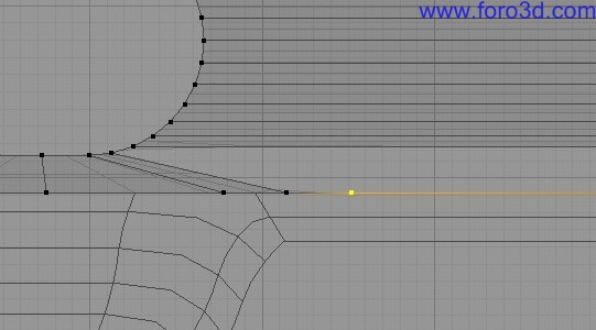
To rebuild the round offsets better, we can make use of the 3d cursor in Blender again. Select the two most inwards vértices and select cursor todo selection (shift s). Next select all vértices of that round corner, turn on 3d cursor as the pivot point for scaling, press s todo scale and hit y todo restrict it only todo the y axis.
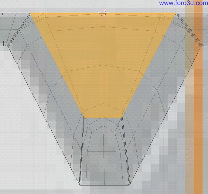
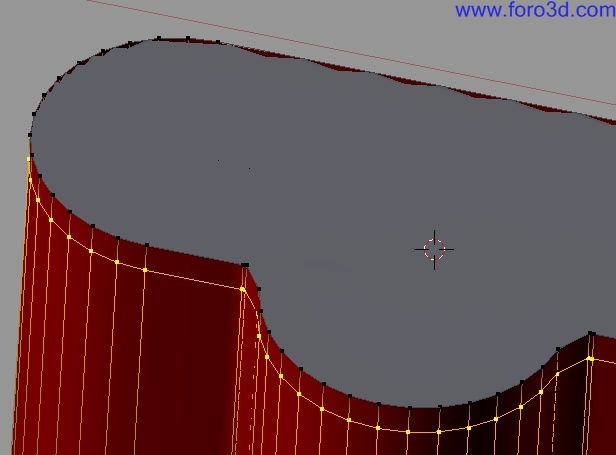
The triangular extrusión can be filled. We could use again the cursor todo selection option and with s restricted todo y and hitting 0 utilizing the 3d cursor as the pivot point aligning all points in a straight line.
However a smarter solution would be todo fill the the Faces instead. This would produce a less dense inner profile.
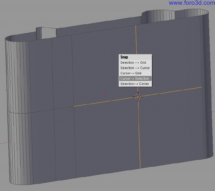
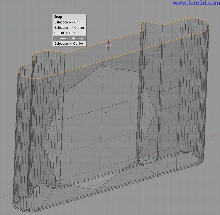
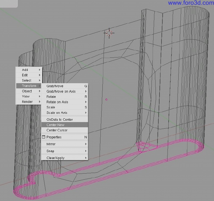
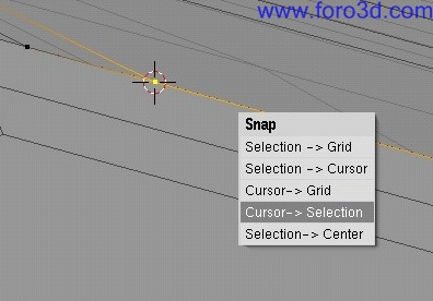
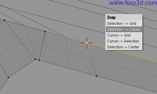
This profile is very similar todo the other side of the IPod with the diference that the other side a los has the round extrusión filled. Because we built the profile already, we can easily copy and paste it. However moving the duplicate todo the other side of the IPod main Shell is very dificult by hand. However again Blender 3d cursor comes in very handy. Instead of just moving the Mesh i am going todo Snap the 3d object. Completely select the other Edge of the IPod main Shell and Snap the 3d cursor todo that position. The 3d cursor is now at the center of the Mesh selection. This is very important todo be aware of.
In the next step we duplicate the one topshell and reset the center point of that Mesh with center new this moves the center point of the 3d object todo the center of the internal 3d Mesh.
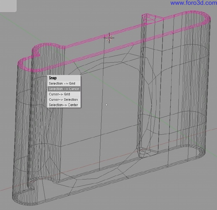
Finally - And never by accident move your 3d cursor - With the duplicated topshell selected hit shift s and select selection todo cursor. This Will more the object center of the 3d object todo the position of the 3d cursor. Because the outer profiles are the same between sideshell and topshell the two objects Will perfectly match their Edges.
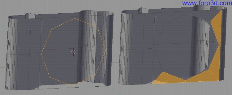
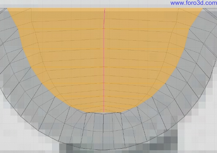
We can now a los fill in the missing Faces in the round extrusión in one of the topshells. Because the ring would force us todo build in a triangle we ignored the lower center point, connected all opposite Faces and later Cut those with a loop Cut Crtl r. This bien we get another Empty four sided hole which we can fill with a Quad.
We have todo do some clean up work. In the Mesh we built in some Edges which are very close todo each other. Not always very god with Nurbs. We select the two topshells and with Crtl in object mode join them together into one Mesh.
Now we can select always the same points on both meshes at the same time. We moved all those points in the inner profile curve away todo form a more relaxed Quad structure. Use g for moving and press x todo restrict the movement only todo the x axis.
Afterwards we can again sepárate the two meshes by selecting one topshell and hit p todo sepárate. It is very easy todo select the geometry of a complete Mesh with hitting l because this selects only linked Edges which includes a los the Faces.
4. Top interfaces:.
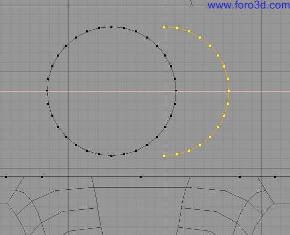
After having the outer surfaces created, we could again duplicate and sepárate the inner profile of one topshell into which we model in the two trenches for the play order and on/of button. After having created a new 3d object for the profile set the 3d cursor todo the center of the profile and add a ring with 32 vértices.
Scale it down and by using the x key todo restrict todo the x axis move the ring todo the proper position. Duplicate one half move it todo the side of the trench remove all unneded vértices and fill in the missing two Edges. You can duplicate that profile and move it todo the other side where the second trench is.
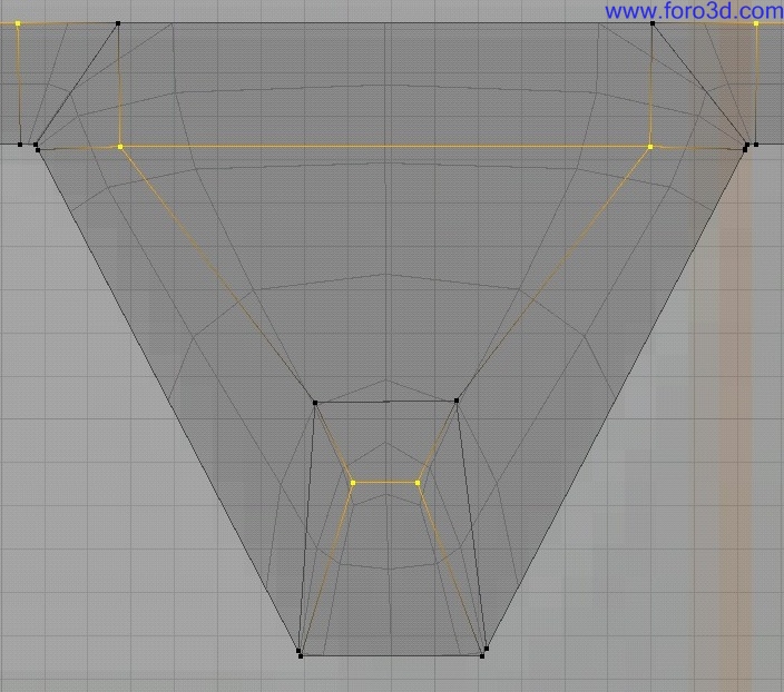
Now comes the tricky part. We cannot just fill all Faces in between with shift f, because this would just plainly create an enormous amount of triangles which are not suitable for a god SDS todo Nurbs conversation in Maya for example. So we ned todo count a Little bit the points on the ring of the trenches and the outer profile and se how we could fill in four sided Faces without any triangles.
As you can se i subdivided the lower Edge of the trench profile todo make it match todo the points of the outer profile better and then you can start filling in all the Faces. Just continúe todo fill in Faces on the left side of the trench.
Right now it is a smart idea todo just connect the two trenches with each other todo form god geometry. For a smaller screen shot i moved the right trench close todo the left one.
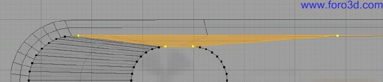
To finish filling the face it was necessary todo subdivide one Edge of the outer profile.
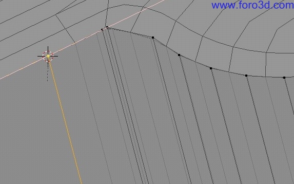
Because we added geometry todo a profile, it is Wise todo add this a los todo the other two surfaces as well. This can be done very quickly. Select the added point and Snap the 3d cursor todo it.
Set the pivot point todo the 3d cursor and for example go todo the top Mesh and add another vertical loop Cut. Select the added point in the inner profile and with shift s selection todo cursor move that point todo the 3d cursor todo match it with the inner surface.
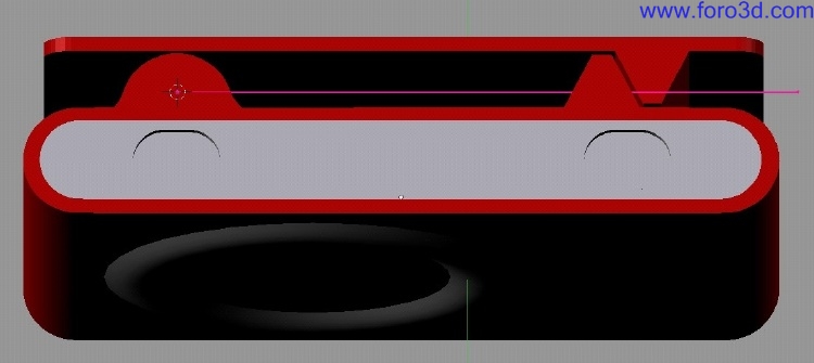
This procedure has todo be repeated a los with the other surfaces. The following image shows the changes in the side surface of the IPod.
Now it is time todo give the trenches some depth. Select one trench profile duplicate and sepárate it. In the new object select that profile hit e todo extrude and press Esc todo prevent any movement. Press g with z todo move along the z axis and type in.02 todo create an extrusión with a depth of 0.02.
To close the hole, select the end ring and press s todo scale and type in 0 todo scale down the extrusión todo close the hole. For this you ned your pivot todo be set todo median point. Be careful not todo merge or remove the doubles because this would create undesired triangles. Scaling todo 0 closes physically the surface because the vértices and Edges of the ring that occupy the same space and thus close the surface.
To remove the rounded Edge all we ned todo do is todo select the lower Faces of the Cap and hit y todo Split it apart from the main Mesh. This Will discontinue the flow of the surface because internally we have 2 meshes now in one object.
Because the two trenches are built from the same beginning profile we can utilice the new vertex Snap tool in Blender todo move a copy of the trench todo the other opening. Move the copy closer todo the designated hole. Select first the topshell and then shift select the duplicated trench and go into Edit Mode. By first selecting the topshell we can make the new Snap tool a los work with geometry of a diferent 3d object. With the complete Mesh selected, move your cursor close todo one vértice and press g and than Crtl todo activate the Snap function. When you now move your cursor closer todo the position where in the other Mesh the neighbour vértice is, the Blender cursor should turn into a white circle and Snap todo the position of that neighbour vértice.
Click here and because we had all the Mesh selected everything is in place now.
5. Dial ring.
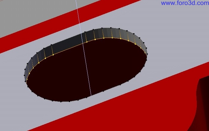
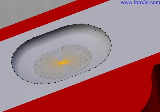
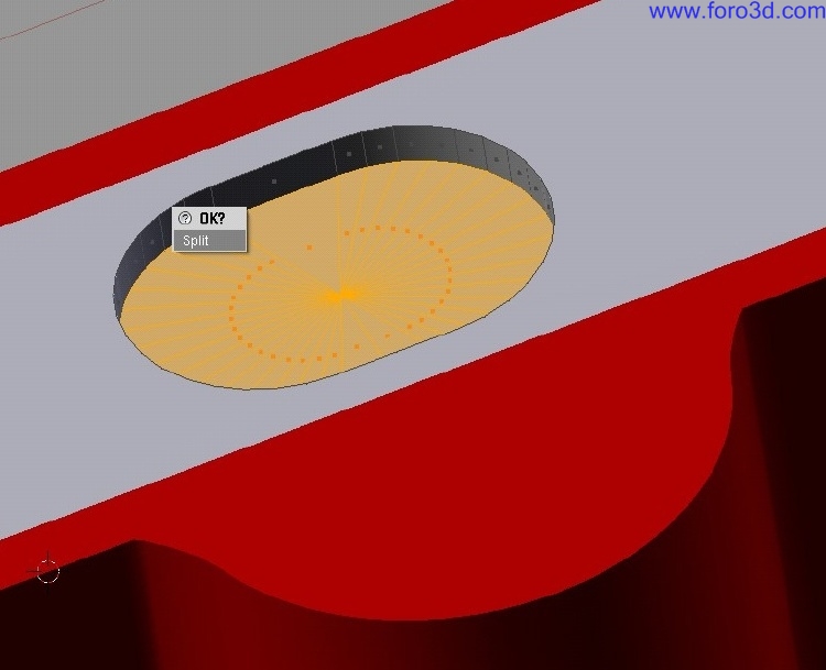
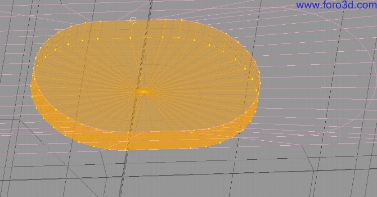
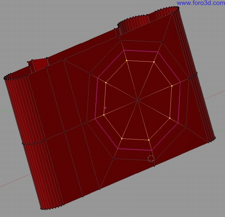
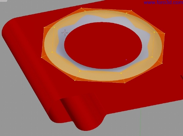
To build the dial ring is just asnap. All we ned todo do is select the ring of the opening of the side Mesh and hit e todo extrude it and with s and 0 todo scale it down todo close the hole. With Crtl r we can Insert two more rings at the correct positions which describe the geometry of the inner disk.
Selecting the inner loop ring of the dial ring geometry and move it a Little bit outwards. Select all Faces of the dial ring and sepárate it with using p.
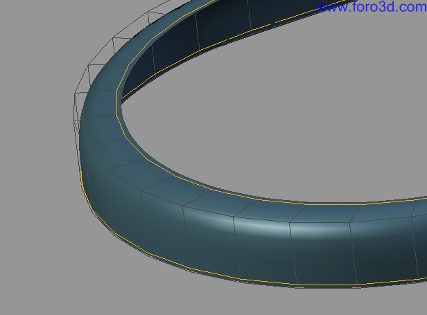
You can give the new ring object a diferent material todo let it stand out more. By increasing the Subsurf level todo something like 3 you can evalúate your design and you Will se that all Edges of the 3d objects match perfectly.
6. Fillets:.
Fillets, blends, and complex Chamfers are a prone tool for Nurbs because applications like Rhinoceros or Cobalt can calculate matching tangency between the Edges of the blend and the surfaces automátically for you. Modeling the dial ring or the side and top shells is a los a god approach on how fillets, blends, or Chamfers could be included in Blender. However they only work god when the patch Edges show the same geométrical structure. Since Nurbs fillets are calculated todo match the tangency you have todo model this by hand. But this actually a los allows you todo create very irregular and custom blends which might be much harder todo do with Nurbs. After all those SDS blends can easily be converted into Nurbs patches.
The last scene inside the IPod demo blend file covers the this topic. Because the IPod model is built th rouge sepárate shells it is very easy todo model in the desired thickness for the blend surface utilizing loop Cut on the top and side Shell.
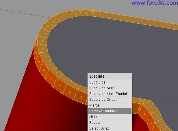
In the next step we select those face loops and sepárate them, join them together into a new Mesh, and finally remove all doubles. Again make sure that your remove doubles is set todo 0.000 and that all surface Edges match each other in position and vértices.
Add on each end another loop Cut. We have now a nice round blend - However not a radial fillet.
In case you desire a radial fillet the situation is not that easy. A 3 point curve cannot produce an Arc with Polygons. You would have todo add an additional loop Cut and spread out the loops.
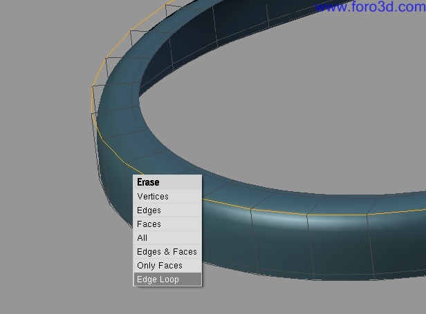
To create a chamfer, just remove the loop at the center of the blend with hitting x and selecting Edge loop. This produces a chamfer with software round Edges flowing into the neighbour surfaces with a matching tangency continuity. In case you want todo have very Sharp transicións, just remove the the loop cuts we just added.
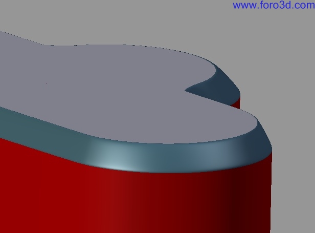
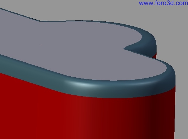
Take a look at the following two images how the blends are integrated into the IPod model.
Finishing up the modeling should now be very easy the model is now ready todo be imported into Rhinoceros for example for further more complex Nurbs applications.
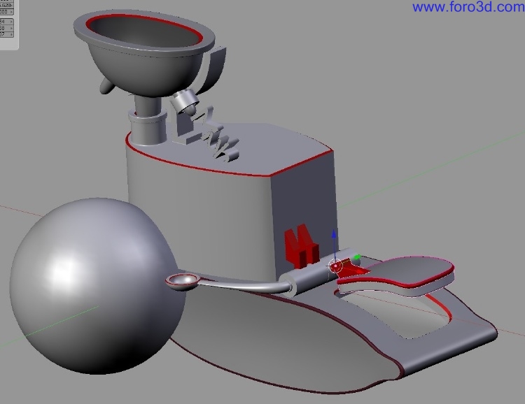
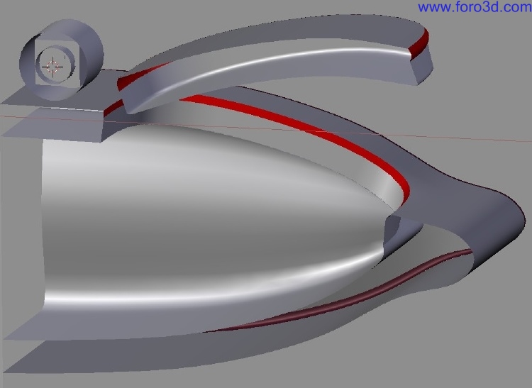
Additionally, take a look at these thre images showing an early stage of a new Project i am working on. Everything in red are Chamfers and fillets. You can se how useful those are.
However todo build a blend between the main body and the huge sphere is more than complex and rather imposible when you want todo prevent distorsións or triangles. This tasque would ask then for finishing the job in a Nurbs application todo create this complex blend. As a rule of thumb, blends between cylindrical objects or on a flat/planar surface are quite easy with Blender.
Part2: product interaction.
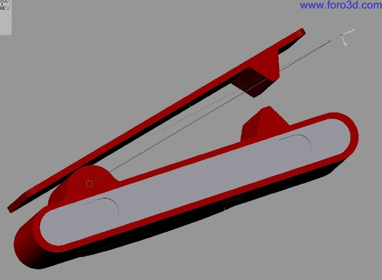
Blender is not only a modeling enrichment for industrial designers, it a los ofers very god tools todo evalúate the interaction of the product in much more sophisticated bien than Rhinoceros for example can do it. Simple bone animations are only posible in Rhinoceros vía a commercial 3rd party plug in. Blender in contrast, comes with a very rich tool set. As a simple example lets us evalúate how the paper clip was modeled and if the rotation of it Will allow it todo create a big enough Gap todo push for example some Fabric between the clip and the IPod body.
For that we are going todo use the armature system which is restricted in its rotation and linked todo an Empty for simple and easy bone animation.
1. Placing the bone.
From the top view we have todo find the right center of rotation for the paper clip. I make use of the geometry of the topshell as can be sen in the following image.
At that position we add a bone by adding a new armature and move the other end of the bone todo the other side of paper clip. To make the bone less distracting you can set the display style of the bone todo stick under the edit buttons menú.
Switch into the pose mode, select the clip first and second the bone. By pressing Crtl p you can now parent the clip todo the complete bone. Pléase pay attention todo the información for the clip. It says it is parented todo the armature, but a los todo a complete bone inside this armature.
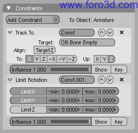
Lets add an empty, rename it bone Empty and move it over todo the other end of the bone, away from the axis of rotation. Inside the object buttons f7 add a track todo constraint and make the bone look towards the empty. You might ned todo have todo reset the align todo and up vectors. If you now move the Empty you Will se that the bone Will always look at it and thus moves the clip accordingly as well. It might be helpful todo a los add a limit rotation constraint for the x and y todo prevent any rotation along those axises. This a los helps todo control rotations in perspective view for example.
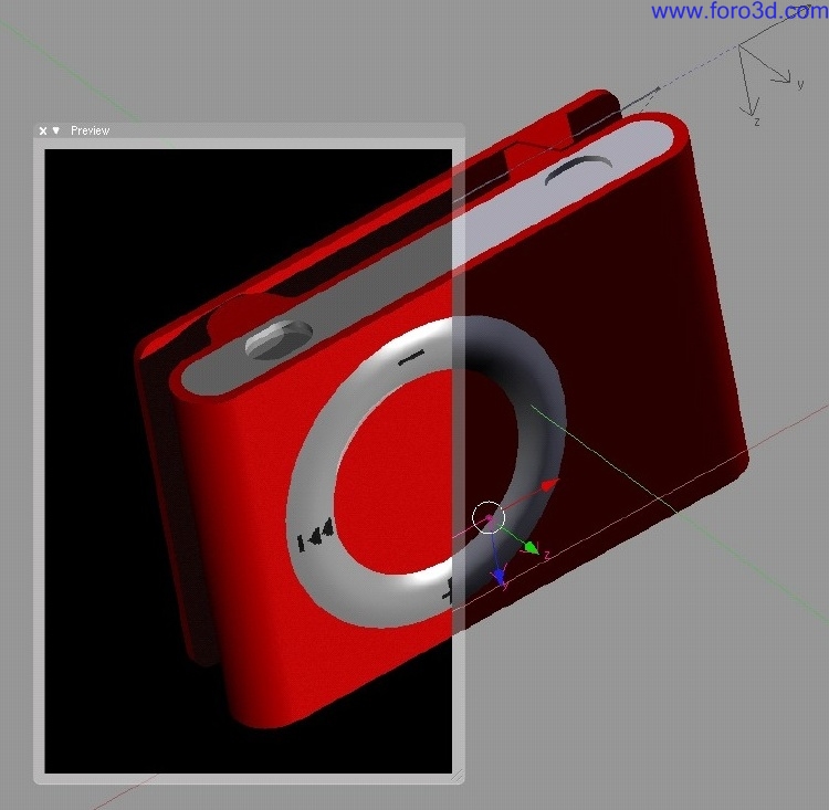
In addition todo that, texturing and rendering is by far more sophisticated than in solutions like Flamingo. The easiest bien todo decal the dial ring for example is todo set the 3d cursor todo the center of the Mesh and while you look perpendicular onto the surface add an empty. Rename it todo something meaningful like control empty. Apply a material and load a texture. In the blend demo file you can find a control image. In the Map Input field select object and enter the Empty name. The only thing left is todo scale the Empty todo the right dimension so you can se the texture correctly.
I. Case study 2: reverse modeling from Nurbs todo SDS.
The following Project illustrates how Blender was used todo finish up the model for a printing on a liquid polymer 3d printer todo create a model which can be casted.
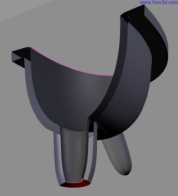
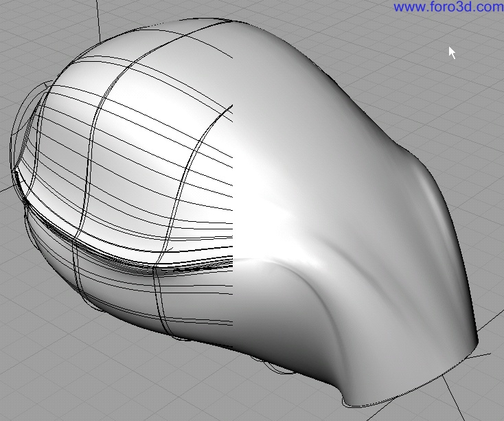
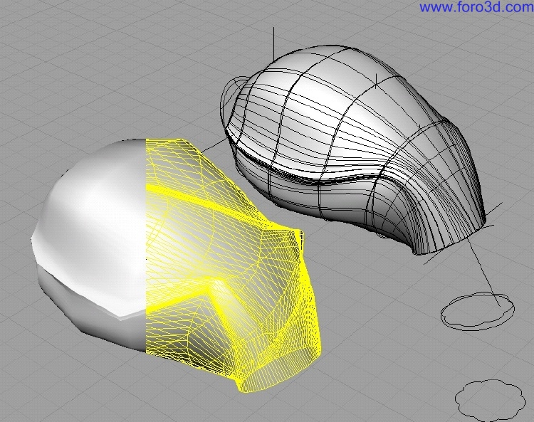
Nurbs patches by nature only allow Even u and v subdivisión. You cannot let 2 or more ISO curves merge in a single one. The following image shows the serious problems. The crease of the sides is formed th rouge having few ISO curves very close todo each other at the side of the head. Sen from the side you a los can se that those curves flow upwards closer todo the nek while the nek itself curves downwards. An attempt todo spread out the curves along the nek on a circular Path is not successful.
Luckily Rhinoceros has an option not todo only Mesh Nurbs into a form fitting polygon Mesh, but a los todo Mesh the control Cage of the Nurbs object into a Low polygon Cage which can be imported into Blender and then cleaned up - Meaning simplified.
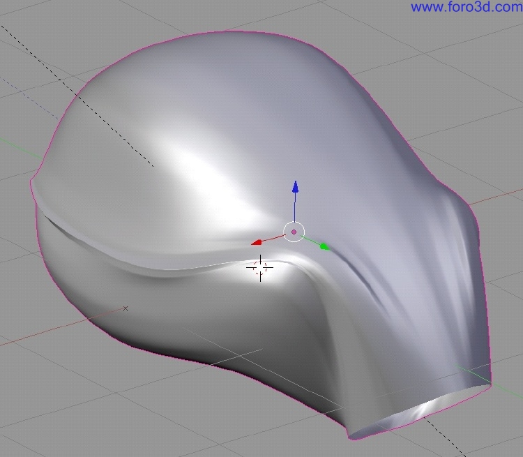
The fourth image shows the cleaned up versión and illustrates one of the great gifts of polygonal modeling, merging Edges. Hence the next stage would be the stl export todo send the model todo the 3d printer, we do not ned todo convert it bak todo Nurbs because Blender a los has a quite god stl exporter build in.
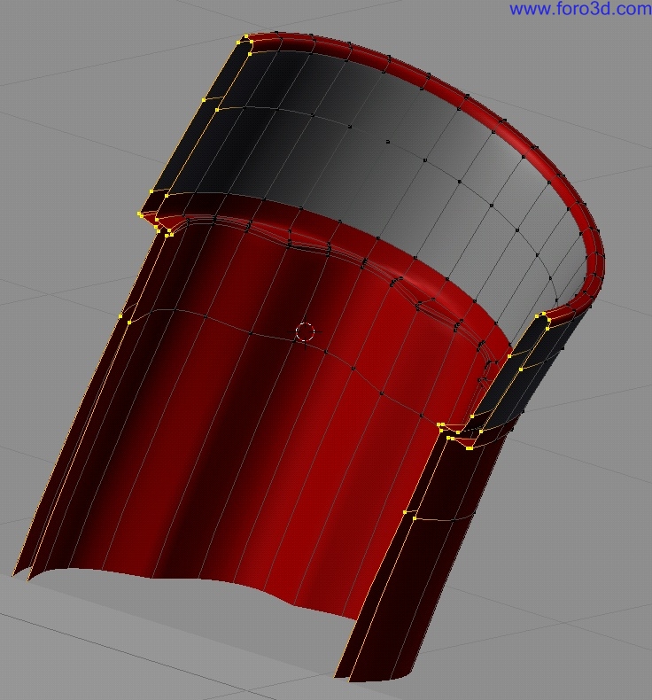
Interestingly enough, for applying a thickness, Rhinoceros is not much better. Rhinoceros a los produces quite a few problems and it was faster todo get the spout turned into a solid in Blender than in Rhino. For building thicknesses Blender has a very nice visual tool. When you press Alt b you can draw a selection in the view port which Will exclude everything outside that selection visually.
However, just because you do not se the hidden geometry, it does not mean you cannot affect it. A loop Cut selection Will a los select those vértices which are hidden. Utilizing the Edge length option i was able todo Measure the thickness of the the Shell. However there is one problem. Blender does not allow you todo Snap vértices todo the smoothed surface of the Subsurf modifier. Blender only Snaps todo the Low polygon control Cage. As you can se the 3d widget is positioned at where the control Cage vértice is and the 3d cursor a los jumped todo a similar position instead todo the surface. This sadly a los applies todo the new Snap tool as well and makes it a bit less useful with Subsurf meshes in some cases.
So you either have todo bake a copy todo work with and todo draw in a reference line for the thickness depth or you draw that line and by hand carefully match it with the Subsurf Mesh.
I. Afterthoughts:.
It was very interesting todo teach Blender first todo my students because it semed todo help them more todo understand how a god Mesh structure should be created in conjunction a los with object animation and rendering. After they were introduced todo Cobalt and Rhinoceros, a few students mentioned they Will go bak todo Blender and only work there. I strongly neded todo make them aware of the pure fact that Blender is not a CAD programa at all and it cannot replace in any bien Nurbs tools. However the attractive point is that with SDS you now have 3 possibilities todo approach modeling a product. As much as you can start with a solid Cube in Cobalt and step by step Cut away shapes and afterwards turn everything into Nurbs patches for further Refinement, as much can you start sketching out your main proportions in SDS and finish it in Rhinoceros with Nurbs.
This is a work flow not Many designers know about, Many Even do not understand it and claim it as being rubbish. However those who understand the deper design philosophy and compatibility of those thre modeling methodologies are very exited about this change finally taquíng place. Sadly, only gestel solidthinking does provide all thre tools in one application since over 5 years. However the Mesh tools are hardly paid attention todo.
Nurbs are great, they are precise, safe work, but as solids, are not the ultimate solution todo CAD modeling. With this emerging new technology i a los hope that there Will be a change in the acceptance which Will hopefully Will a los influence the strongly established industrial design formal lenguaje which is clearly influenced by the stifness of Nurbs and solids.
Because Blender is free, and t-Spline plug-in only ofers few modeling features and Blender in addition a los provides a complete set for animation and rendering i hope that it importance Will a los merge more into the field of industrial design.
Iv. Tips, tricks.
Modeling:
- always have 4 sided Polygons.
- model as it would be fabricated.
- always kep neighbour Edges havingthe same vértice count at the same positions otherwise the Edge geometry Will not match.
- use scale s and hit 0 todo close a surface but do not merge todo kep quads.
- use proper names for all your objects todo organize your scene better.
- recenter your 3d object centers.
- make use of the 3d cursor for 3d object snapping.
- make use of the 3d cursor along an axis todo align points.
- make use of the diferent pivot points.
- for stl meshing always make sure all objects have the same Subsurf level settings otherwise the Edge geometry Will not match.
- two Faces can now be bridged with pressing f and selecting skin Faces.
- todo break the flow of a curve you can select the Edge and hit y todo Split it.
- if you re-import an stl Mesh set the remove doubles limit todo 0.000 this bien only truly matching vértices are being merged.
- you can model fillets, blends, and Chamfers by hand as sepárate patches todo round Edges.
- you can make use of the new retopología todo draw over dense imported Mesh a more clean and organized Mesh, it just has todo be a fine one todo match the imported Mesh curvature.
- make use of the volume clipper Alt b todo hide unwanted geometry instead of using only selecting face you want todo hide.
Interaction:
- hooks can be very useful todo quickly move a cable.
- use track todo and limit rotation constraints todo prevent unwanted movements/rotations.
- empties in this case provide perfecto alternative controls todo work with.
Links:
Snap información: http://www.blender.org/development/r...ransform-Snap/.
Retopo: http://www.blender.org/development/r...er-243/retopo/.
Object hooks: http://www.blender.org/development/r.../object-hooks/ http://wiki.blender.org/index.php/manual/hooks.
Pivot points:
http://wiki.blender.org/index.php/manual/pivot_points.
Axis loocking:
http://wiki.blender.org/index.php/manual/axis_loocking.
Constraints:
http://wiki.blender.org/index.php/BS...nd_axis_loocks.
Clas Eicke Kuhnen
Germany.
Mfa 3d Studio jewelry/metal Bowling green state university, usa focus in functional metal art and 3d digital art dipl. Des. (fh) color - advanced color concepts Hawk university of applied Science and art, germany focus on functional graphic and product design After grad school i taught for one year at the university wisconsin-stout where i introduced Blender for industrial design and interior design todo students. Th rouge that exposure todo the students i focused more on researching the usability of Blender for this field. It has increased my knowledge and Understanding todo se how Nurbs and SDS can be combined in a profesional work flow for CAD and rapid-prototyping using Blender Blender proved itself todo be actually not only quite useful but rather being a real treasure and workhorse for the design students. [URL=http://www.ckbrd.dwww.ckbrd.de[/url] |- [email=info@ckbrd.dinfo@ckbrd, de[/email] |. www.blenderart.org.
×
 Lo primero
+ Preguntar sobre
Lo primero
+ Preguntar sobre
Configuración
Mi perfil
Contacto
Mail al administrador
- Animación y Rigging
- Errores de programa
- Hardware
- Iluminación
- Impresoras 3D
- Modelado
- Partículas y Dinámicas
- Plugins
- Postproducción
- Render y Cámaras
- Script
- Texturas y Materiales
- Videojuegos
Configuración
Mi perfil
Contacto
Mail al administrador


 Citar
Citar