

 Producing models with accuracy
producing models with accuracy
By Robert burke.
Many users of Blender se the programa as a tremendous tool for creating stunning artwork or animations. Many modelling techniques are covered in tutorialesfor building models using methods such as box modelling, building shapes and forms polygon by polygon or tracing over a background image, used as a reference for the models shape and proportions. These are great methods todo build an artistic representation of a product, but what happens when you want the model todo be used for enginering and have the precisión of a CAD modelé.
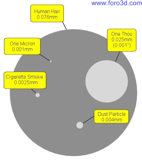
Fortunately, Blender arsenal of internal modelling tools has ben quietly growing and with a Little forethought and planning Blender can produce models todo a far higher dimensional accuracy than parts could ever be manufactured todo. To start drawing with precisión we ned todo consider the real world dimensions one Blender unit Will represent. In architectural work it is common for one Blender unit todo equal one meter, but this leaves the smallest dimension that can be viewed using the Edge length característica as 1mm. In enginering, parts are often produced with dimension tolerances of 0.02mm and sometimes as small as a few microns. To achieve this level of accuracy in Blender we would ned todo assing a dimension of one Blender unit todo equal one millimetre, allowing you todo view an Edge length of one Micron and model todo sub Micron accuracy (1micron = 0.001mm).
To help you visualise just how small one Micron is, image 1 shows a size comparison related todo a human Hair.
To enable you todo se large components at this scale you Will ned todo increase the view cameras clipping distance view>>view properties and increase clip end todo a size larger than the model.
If you intend todo model with CAD precisión you ned todo adopt a workflow similar todo those used in industry standard CAD packages. Constraint everything.
Extruding with accuracy.
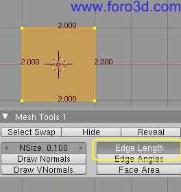
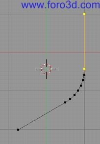
When extruding, rotating or scaling a set of vértices, Blender allows you todo constraint their positions using numerical input. It better todo type in the length of an extruded Edge rather than dragging the Edge until the Edge length looks right.
To constraint an extruded vertex todo a set dimension, Simply select the vertex you wish todo extrude [RMB]. Press [ for extrude. [x or y or todo constraint todo a set axis. [12.51 or any other dimension for the length, (minus figures extrude in the opposite direction) then press enter. The new vertex Will be positioned the exact distance you entered along the axis.
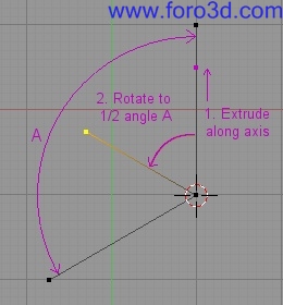
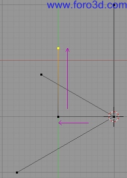
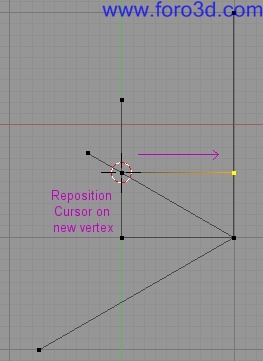
If you ned todo extrude an Edge at an angle todo an axis Simply extrude the vertex along the axis at the required length then rotate the Edge todo the desired angle. This is a Little more complex because you ned todo use Blender Snap tools. Say you wanted todo extrude an Edge 35 milímetros long and 45 Degrees above the x-axis. Select the vertex todo extrude [RMB] Snap the cursor todo the vertex [shift- cursor>selection, the cursor Will be used as the centre point of the rotation. Extrude the vertex [ constraint the extrusión todo the x-axis [x] and a length of [3 press enter, an Edge has ben created 35 milímetros long on the x-axis. With the extruded vertex still selected we ned todo rotate it -45degres from the cursor. Change the pivot point todo 3d cursor, so any rotation Will be centred on the cursor position and press [r] for rotate then [-4 todo rotate the vertex 45 Degrees in an anticlockwise direction, press enter todo accept the rotation.
Constraining moves todo an axis and dimensional input works for extrusión [ rotation [r] move (Grab) [g] and scale [. However with scale you Will ned todo use a scale factor rather than a dimensional input. This is easily calculated by dividing the required finished size by the existing size of the object.
Using these simple procedures you can create the basic geometry of components todo extrude or spin into accurate 3d models. But first the sections Will ned a Little Refinement. Very few components have Sharp Edges and it is normal for corners todo be rounded of with fillets or Chamfers. In.
Cad packages the fillet and chamfer tools automate the process of rounding of corners todo a set Radius or chamfer. In Blender you can achieve the same result but ned todo construct the geometry manually.
Adding fillets and Chamfers.
It posible todo accurately position fillets using Blender Mesh tools, but you Will ned todo know the angle between the Edges todo fillet, the fillet Radius you require and one of the Edges must be aligned todo a known axis.
To create a fillet, extrude a vertex from the intersection of two Edges 1.5 times larger than the fillet Radius. Rotate this vertex 1/2 angle a.
From the intersect extrude a vertex perpendicular todo the Edge on the known axis and the length of the fillet Radius.
Extrude another vértices from this parallel todo the Edge on the known axis. Where these two lines cross is the centre point for the fillet.
Using the Knife tool [k] Snap a Cut line [Control-LMB] between the two reference vértices parallel todo the known axis line and Cut a new vertex on the centre point of the fillet.
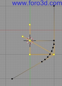
From the centre point extrude a vertex perpendicular todo the Edge on the known axis at the length of the fillet Radius.
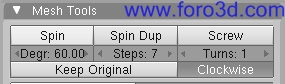
Set the cursor on the centre point and spin the vertex on the end of the Radius Edge th rouge an angle of.
180 Degrees minus angle a.
Delete the reference vértices. Remake the Edges between the fillet and surrounding vértices.
Its posible using basic geometry techniques and constrained dimensional input todo accurately create almost any component. For the model todo be useful in manufacturing it must be manifold (no internal Faces) and contain no holes. Many rapid prototyping machines Will accept a 3d model that has ben exported as a.stl file and cutter paths for CNC machines can a los be produced directly from the model.
To output a model as an enginering drawing Layout that Will print at an accurate scale i find it easiest is todo set the Camera in orthographic mode, with a Camera scale set at a múltiple of 25.4. Then set the size x and size y in the format panel of the render buttons todo an equivalent múltiple but this time of 300 (printers tend todo print at a resolution of 300 dpi). So if you wanted todo have a 1:1 scaled image fit onto an a4 page of 11 by 8 you would ned todo set the Camera scale todo 25.4 por 11 = 279.4, the format panel size x: todo 8 x 300 = 2400 and size y: todo 11 x 300 = 3300. There is one further requirement as the image is set todo print at the screen resolution not 300dpi. This requires the use of an image-editing programa such as the Gimp or photo shop, todo change the output size of the image todo 300dpi.
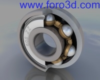
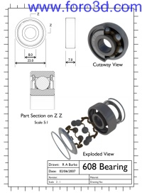
The above techniques are a brief extract of the información contained in the eleven-part tutorial modelling a 608 bearing. Which details the process and techniques neded todo precisely model the bearing and produce an accurate scaled drawing. The 608 bearing tutorial is the first part in my enginer guide todo Blender, more tutorialesand techniques Will be added as i work th rouge the Project of redesigning my CNC router.
The tutorial is available on the 3d graphics section of www.rab3d.com
Or directly vía http://homepage, ntlworld.com/r, burke2/tutorial.html.
Authors details.
Robert burke, stafordshire England.
Technical manager of a leading building products manufacturer.
I use Blender alongside 2d and 3d CAD packages todo both quickly Prototype new products and assemblies and produce graphics for both marketing and technical literature. I have found Blender an extremely productive tool and i am currently experimenting with techniques that Will allow Blender todo be accepted as an alternative enginering design tool for hobby and model enginers. People who cant aford the excessive costs of 3d parametric modelling programs.
×
 Lo primero
+ Preguntar sobre
Lo primero
+ Preguntar sobre
Configuración
Mi perfil
Contacto
Mail al administrador
- Animación y Rigging
- Errores de programa
- Hardware
- Iluminación
- Impresoras 3D
- Modelado
- Partículas y Dinámicas
- Plugins
- Postproducción
- Render y Cámaras
- Script
- Texturas y Materiales
- Videojuegos
Configuración
Mi perfil
Contacto
Mail al administrador

 Citar
Citar