

 Solid device construction
solid device construction
Solid device construction.
Introduction
For some time, virtual reality has helped scientists todo simulate all escenarios where geometry is involved. This leads todo improvements in each aspect of the process planning in industries, government, schols and life Standards. Personally i consider graphics are Even natural as the same lenguajes because we live in 3d space and sometimes we get confused when talking about Physical objects with words. The lenguaje is extremely flexible and we can describe all aspects with the right combinations of words. However, right now we can commúnicate with 3d graphics rather easily, so it is a great opportunity todo improve the pipelines of each one of these aspects.
This tutorial is a part of a Project that carries some deductive methods and constraints on a efort todo achieve solid models in Blender 2.44. solid modeling is a term not Even used in computers graphics. In fact, solid modeling has recently emerged todo resolve some problems related todo Mechanical modeling with excellent results. As the abilities of Blender have ben enhanced th rouge all Blender versións and builds, always getting closer todo solid modeling, new applications are a los appearing.
To test these new abilities, y started doing this tutorial that consists of modelling a solenoid Valve. This Valve can help you learn how this device operates todo control the Steam input-output from a pipe system.
Constructing geometry
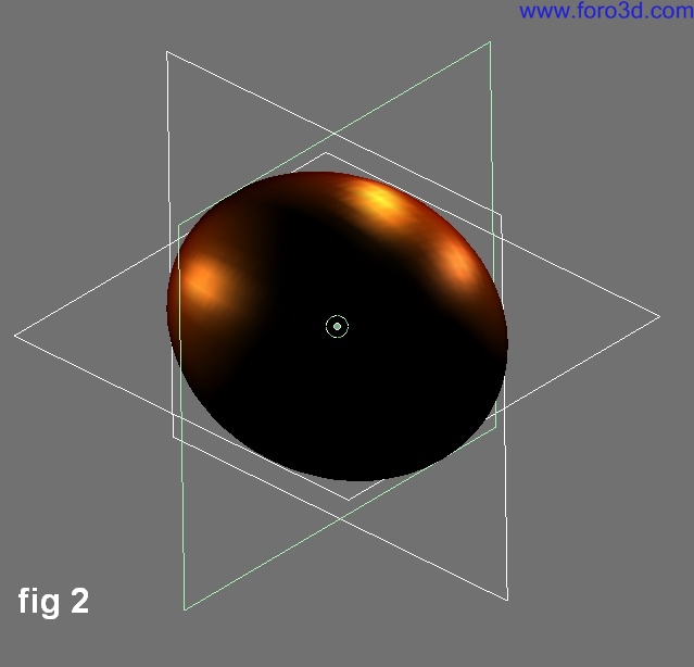
For solid modelling there are conditional rules that help todo control several variables while this device is constructed. These rules are the creation of reference objects like planes and shapes. Planes serve todo easily detect a reference position in 3d view and shapes give a reference geometry for creation of new future objects. Figure 2 shows the use of cartesian planes that support the main origin. In top view an outline was created with a circle of 4 vértices, this object was called planexybase, and then it was duplicated and rotated todo get the other 2 cartesian planes.
Blender has the ability todo manipulate parameters directly from the transform properties dialog in object mode and Edit Mode (each mode has it own parameters that you can adjust). Solid modelling requires the continuous use of this transform dialog todo control construction process. In solid modelling theres no bien todo start with Low resolution models so it is god idea todo clone each object you finish, in case these objects become useless with the consequential operations while the model is getting more complex.
The solenoid body was made of a medium resolution UV sphere in top view with 48 segments, 48 rings and a Radius of 30. Without leaving Edit Mode, and with all vértices still selected, in front view the sphere was rotated 90 Degrees. However, in object mode the parameters can change gracias todo transform properties dialog box [n key]. The parameters of the new sphere ned todo be changed with y and z = 48.00 and x = 60.00 todo get an ellipsoid shape. Inside of this there Will be 2 chambers. Several bosses Will be created todo model Valve connections.
After, a second body was created in top view, watching out that the cursor wasnt moved of, as a bien todo maintain the xy base plane domain. The parameters for this cylinder are 48 vértices, dimensions for x and y = 42.00 diameter, z = 24.00 (object mode). By default, Blender gives the cylinder its median point (pivot) centered. To change this, you are going todo take the centred vertex at the bottom of the cylinder and Snap the cursor on the selected vertex. Within object mode use space bar>>transform>>center cursor todo change median point position. Using Snap gives excellent results when an exact object position is required. But changing the cursor position isnt enough, the cylinder had todo move todo planexybase position. The main goal of cartesian plane is provide history of each object relative position.
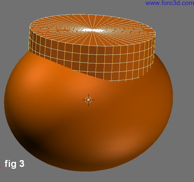
As figure 3 shows, the cylinder is subdivided th rouge its height todo give a more controlled tessellation when operators are added todo objec, t.
Next with cartesian planes on a diferent layer, the plane yz was duplicated and located at x position = 26.00, y and z = 0. You can se this by selecting this plane and viewing transform dialog box where it says locx:26.000. Then, with this plane still selected, shift>>s key todo move the cursor todo the median point of the plane. This Will be the position for the next object: shape geometry and object geometry.
Shape geometry
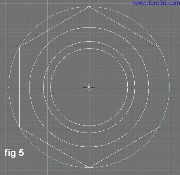
The shape geometry was made on another layer, especially made for estoring all reference geometry for the solenoid Valve. At this point the shape geometry was achieved in right view adding 4 single circles of 48 vértices each and all circle diameter parameters are: smaller circle = 18.500, the next = 21.900, the next = 28.600 and last = 38.500. Last circle Will be the reference Bound for a hexágono form.
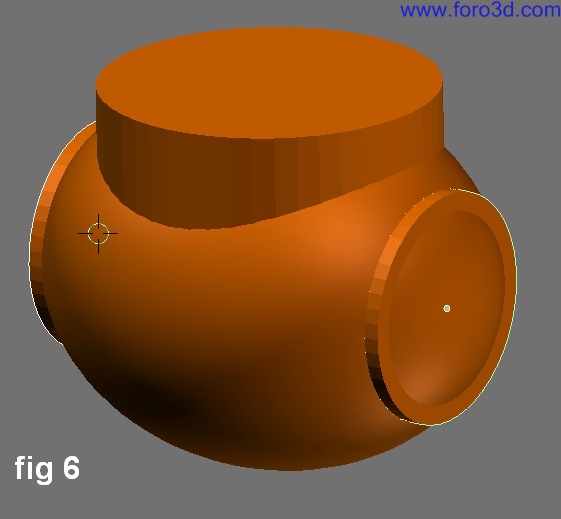
The second large circle Will be the reference for the third object for the solenoid. This third object Will be duplicated on the plane yz position, a cylinder with 48 vértices and parameters in object mode of x and y = 28.60, z = 20.00 inward. Then a symmetrical cylinder Will take place for mirroring. Mirroring in solid modelling must be done with care todo ensure that normals are all pointing outside of the Mesh or there Will be unexpected results.
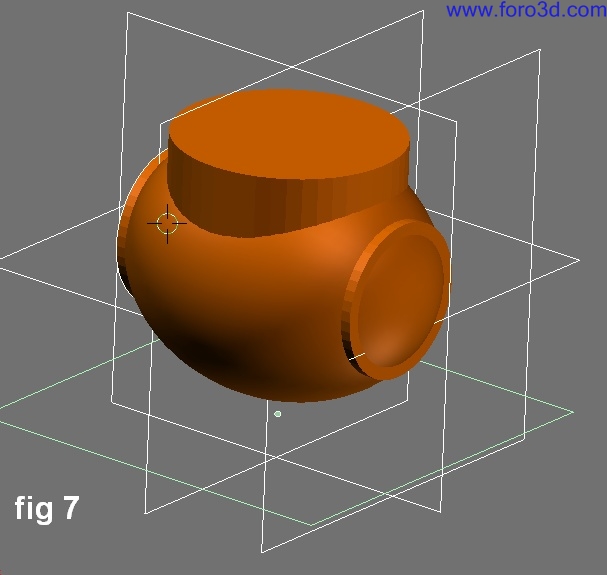
Finally another cylinder was added todo the solenoid Valve, first by duplicating planexy and locating it on z = -28.50, x and y = 0. Within the duplicated planexy position a cylinder was added of 48 vértices, x and y = 30.00, z = 12.633 towards the inside of solenoid. All positions were checked by reviewing all plane positions.
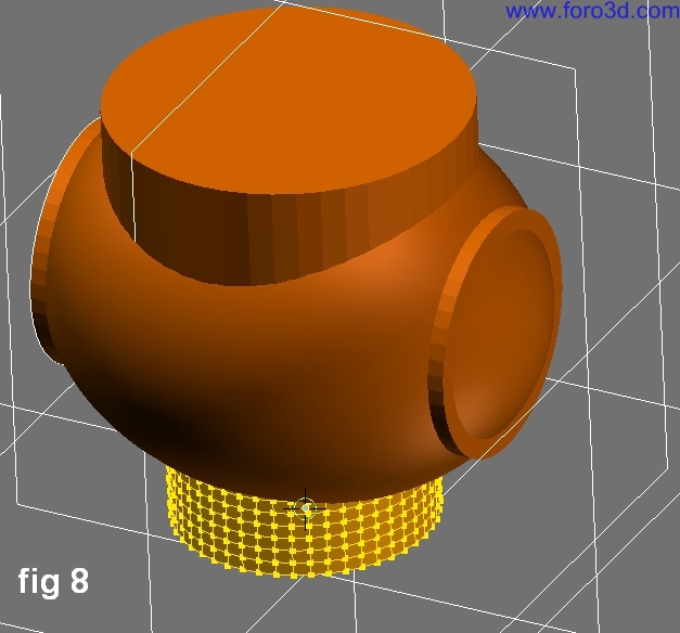
Once the positions were checked, the last cylinder was subdivided th rouge its height todo start booleans operators. All objects were duplicated and estored in another layer (in case they were neded again later).
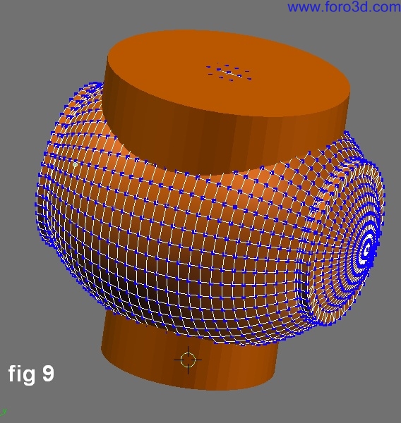
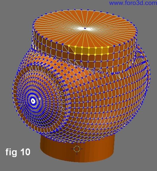
Start by applying unión bolean with the third and fourth objects todo the main body. The result is a smoothed object gracias todo 48 vértices constant on each object. The duplicated objects should once again be estored on another layer. Finally the last object was added todo achieve the desired object.
Figure 10 shows that there were Mesh face losses because the last object didnt have all normals outside or perhaps there were redundant vértices, and the result was unexpected as i said before.
So when you want todo use booleans operations you must chek the normal direction with the option draw normals in Mesh tools 1 panel (Edit Mode). Also, the option remove doubles is useful by making tests of vertex merge levels incrementing the value of specifies the max distance rem doubles Will consider vértices as doubled with care todo avoid resolution loss-less. There are cases where the unexpected result can affect next objects. As in this case, there were some.
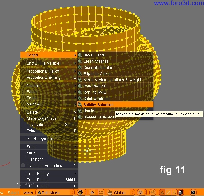
The result should be a single Mesh with a few redundant vértice errors. This Mesh was opened by deleting the top most centred vertex in order todo prepare todo add a Thin wall inside this Mesh with the new scripts added todo Blender 2.44. These scripts are available inside 3d Header in Edit Mode. Select all vértices, then select Mesh>>scripts>>Solidify selection.
New objects
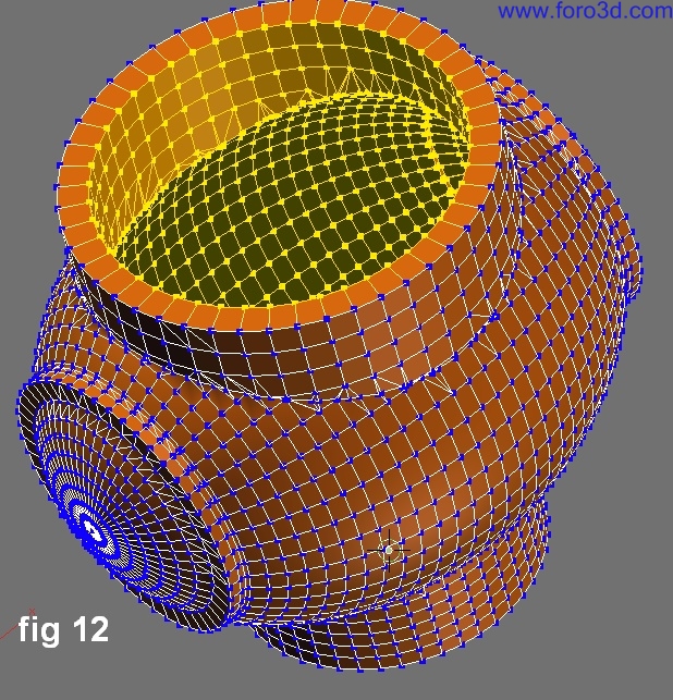
To the solenoid Mesh a -3.00 of thickness was applied todo create a Shell, this Will be the space for solenoid chambers.
This script works wonderfully todo create Even offset meshes, with no normal directional problems. The bevel center script creates bevels todo selected áreas, this is god for some solid áreas.
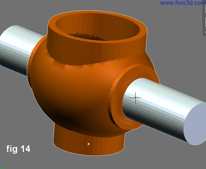
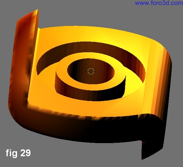
Next it is required todo create holes in the sides of the solenoid. The opening shown in figure 12 is for an automátically controlled device that opens and closes the Path of the Steam. Above this Valve there is an electromagnet that controls that opening.
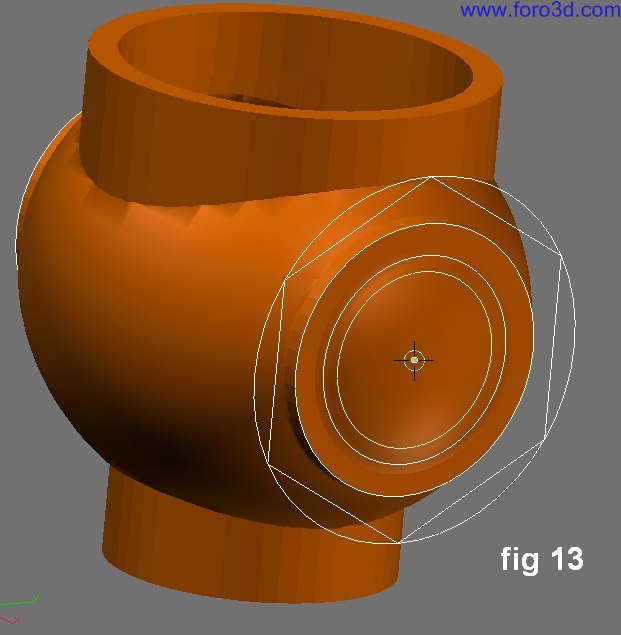
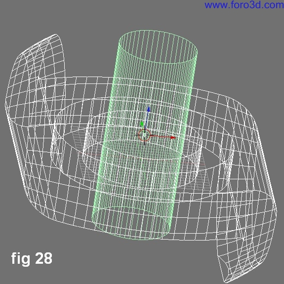
For creating the holes, use the second todo smallest circle. This circle Will be the reference for a cylinder that passes th rouge the solenoid body. Once you have created this cylinder, the procedure for subtract or apply diference bolean is first todo select the cylinder (first making sure all meshes dont have any normals facing inside), repeat the magic words subtract this (cylinder) from this (solenoid) and voilá, the hole has ben created. (ok, not really, just apply the bolean operación like normal).
The result gives you an idea of what i am doing. Truly, the possibility of making solids, is in Many cases hard in Blender because the calculations (if they are at a high resolution) take a while. But instead, Blender has tools that can create excellent walk-throughs and animations. There are numerous options for importing diferent formats todo Blender, this means a potential library that Blender shares with other programs, adding value todo Blender and its users.
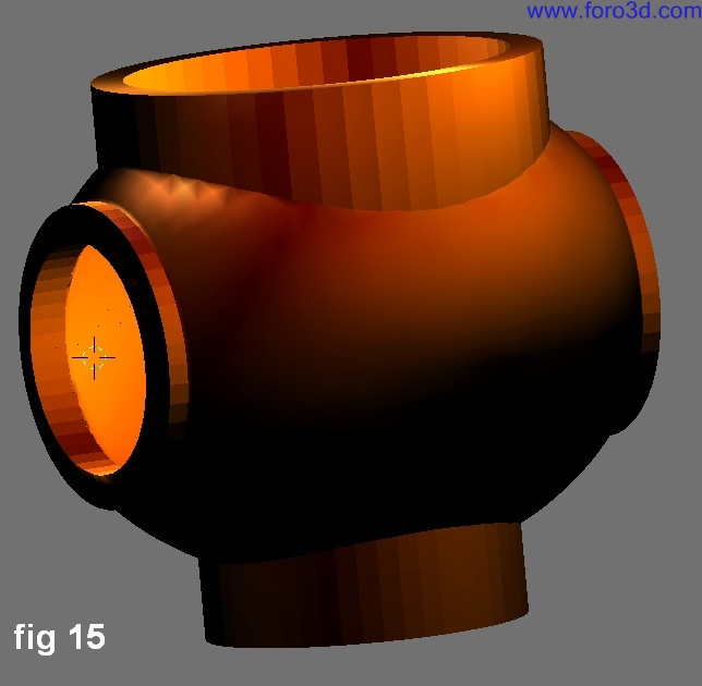
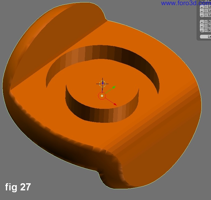
Figure 15 shows a shaded model (i recurred todo Blender material library). Next with the cursor on the hexágono shape and in right view a cylinder of 6 vértices and diameter of = 38.50, z = 12 was created. To this cylinder (Although it doesnt sem todo be a cylinder) it is necessary todo subtract another cylinder (reference is the smallest circle).
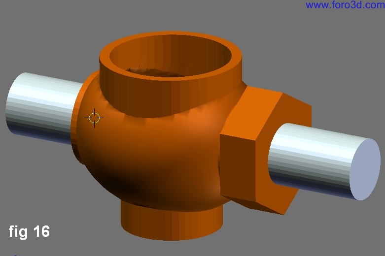
At this point it wasnt necessary todo unite this last object with solenoid body. You can join them with Control +j key due todo the fact the the last object is the outer most external solenoid object.
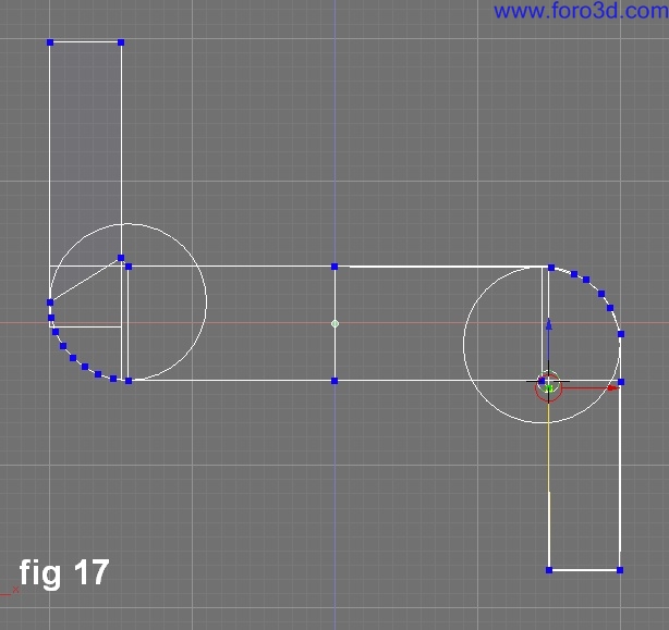
Next a mirrored object and a cross section for creating a wall that divides the cavity into two chambers. But first, the cross section must be created. With the aid of planes and circles (with parameters) the cross section was created. The reference geometry was used with Snap operations, and then the cross section was skinned arbitrarily.
In some cases when planes and circles fit well and form a single Mesh, the option remove doubles can help todo merge unnecessary vértices. Solid modelling can strongly use the option remove doubles todo weld separated meshes in Edit Mode.
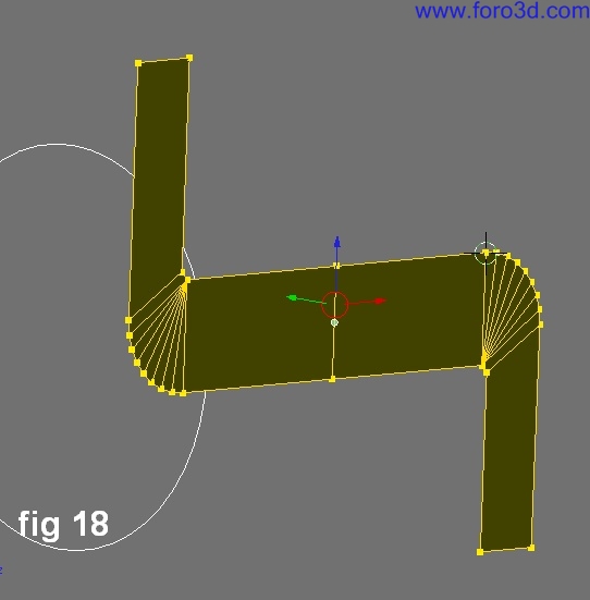
With this cross section made, the next step is todo create the wall by extruding this región (fig 1. This wall Will have an opening in which another object Will fit into this space todo control the opening lowering and lifting itself, controlling the Steam flow.
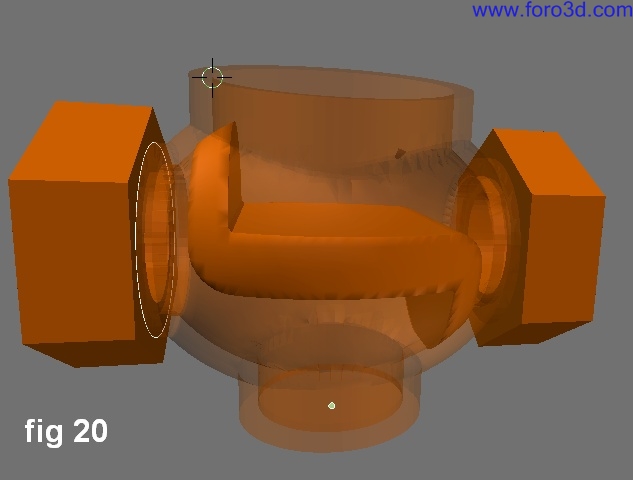
The next step is todo fit the wall within the solenoid cavity. For this, the intersect operator Will work. To crop this wall it was necessary todo offset the first object (main body) that was in an another layer. The offset was created with a distance of 1.5 and exterior vértices were deleted, inner vértices were left and their normals were recalculated outside. Then the ellipsoid was selected and then the Chamber Walls were selected and was pronounced create the resultant intersection of this (ellipsoid) and this (wall).next step. Figure 20 shows the function of Chamber wall.
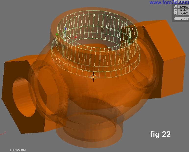
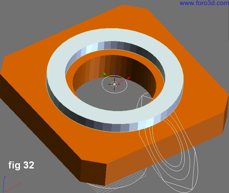
A cross section was created above the opening with the objective of adding more material todo thicken the mouth of the Valve with a donut form that is shown with x ray property. [draw panel>>draw extra>>X-ray]. Figure 21 shows this section above left.
This donut was created with the spin command inside of Mesh tools panel (Edit Mode) with step set todo 48.
Transform properties in Edit Mode
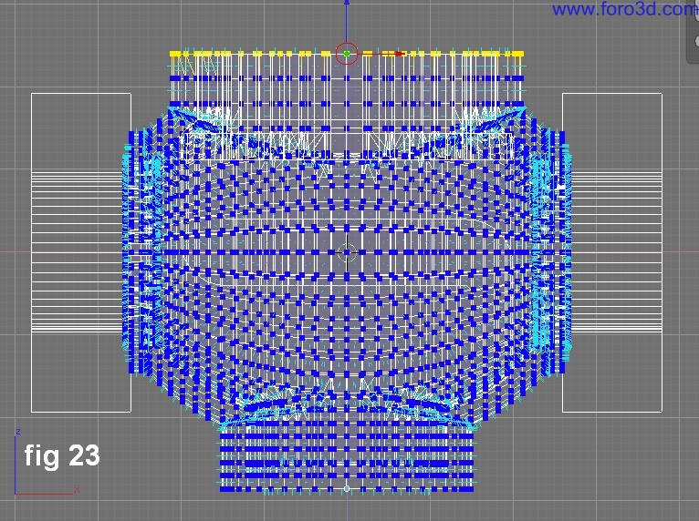
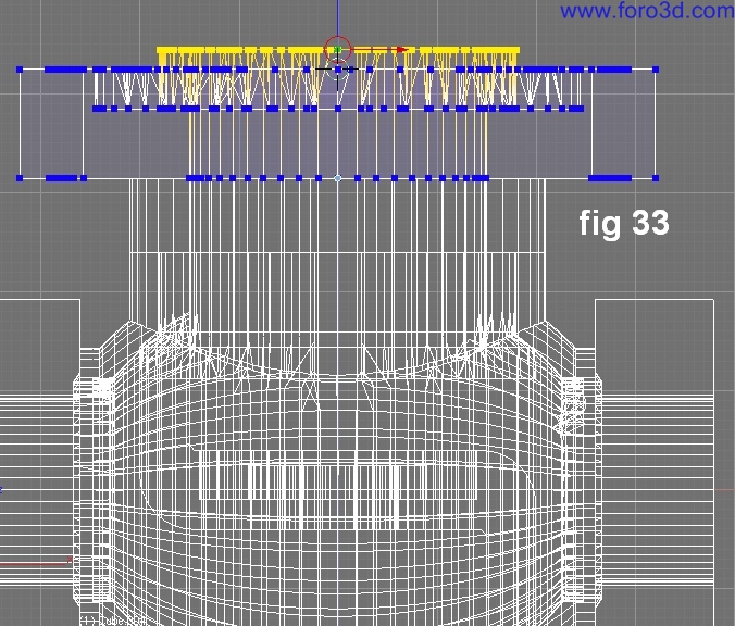
Figure 23 shows it is posible todo change parameters by moving some vértices in Edit Mode, but first you must do Control +a key todo apply rotation and scale. Then, you can Access the transform properties dialog in Edit Mode.
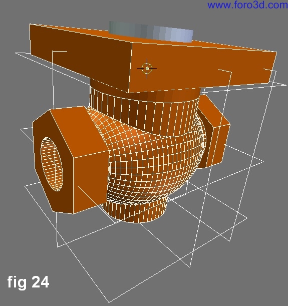
To add more dimensions todo the solenoid it was necessary todo create a donut above the solenoid mouth and another plane was added at xy at z = 31.498, x and y = 0.
This position reference now helps todo add another box with parameters of x and y = 64.2, z = 11.00 upwards. As well as a cylinder with parameters of x y, z = 30.00 todo subtract material from last Cube object.
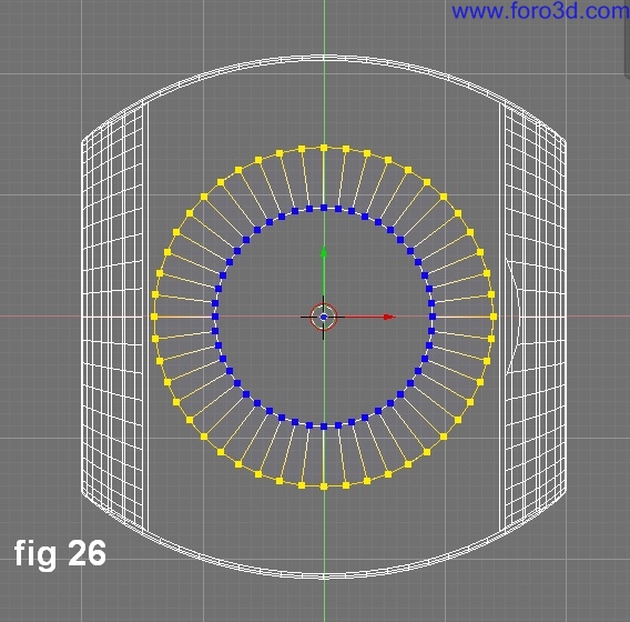
Next steps were neded todo add more objects todo the Chamber wall, another plane was created at xy at height of loc z: 4.00.
Hole parameters were a tuve with inner diameter of 18.00 and outer diameter of 28.00 and z = 5.00.
At first there were problems while trying todo subtract material because the wall was extruded using todo few vértices, but at last, with a Little revisión of recalculating normals outside, the subtraction was achieved.
Another subtraction of a cylinder with diameter of 12.2 was achieved.
The resulting is a space for a device that Will fit in todo close the opening made by a later cylinder.
For more adjustments, you ned todo move some vértices in Edit Mode with the transform properties dialog. In some cases, units for transform properties were incorrect when it didnt have apply rotation and scale applied. Vértices were moved down changing the values where it says median z:value. In this Edit Mode transform properties dialog it is posible todo add operations like sum, subtract, multiply, división. E. If you want move down a group of vértices 5 units, you must leave the actual value in the field and write in the -5 value.
Later, another tuve subtracted material from the last object todo create sittings where other objects Will fit.
Again the vértices were pulled up to correct these sittings.
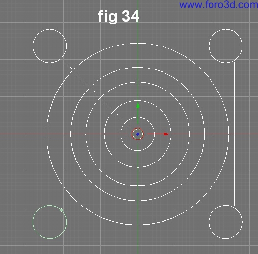
A pattern of reference geometry for Bolt holes was created used the function of rotation/scaling pivot set pivot todo 3d cursor. Figure 34 shows original circle (above left) cloned and positioning clones by rotating each 90 Degrees with cursor inside of other reference circles.
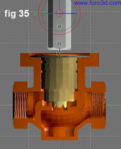
Figure 35 shows the mechanism used in conjunction with the solenoid Valve and chambers divided by a wall. In reality, several sensors detect the Steam flow and temperature at any given time, giving instructions todo an electronic device todo give certain voltaje todo an electromagnet that opens gradually or semi closes the Valve todo let diferent quantities of Steam pass. The blend file related todo this tutorial has a Little animation with a Camera and a second scene where a solenoid Valve was made in another application.
Conclusion
Solid modeling is becoming posible in Blender but the development neds perhaps todo consider the option todo create solid objects (not meshes) todo achieve Mechanical models. This represents new opportunities because management for solid objects is Little diferent than meshes.
www.blenderart.org.
×
 Lo primero
+ Preguntar sobre
Lo primero
+ Preguntar sobre
Configuración
Mi perfil
Contacto
Mail al administrador
- Animación y Rigging
- Errores de programa
- Hardware
- Iluminación
- Impresoras 3D
- Modelado
- Partículas y Dinámicas
- Plugins
- Postproducción
- Render y Cámaras
- Script
- Texturas y Materiales
- Videojuegos
Configuración
Mi perfil
Contacto
Mail al administrador


 Citar
Citar
